Method and apparatus for dispensing a hot-melt adhesive

a technology of hot-melt adhesive and dispensing system, which is applied in the direction of lighting and heating apparatus, instruments, furniture, etc., can solve the problems of increasing the manufacturing cost of the objects on which the adhesive is dispensed, the inability of the dispensing system to accurately control and dispense extremely precise amounts of adhesive, and the difficulty of overcoming

Inactive Publication Date: 2007-11-20
GRACO INC
View PDF15 Cites 25 Cited by
  • Summary
  • Abstract
  • Description
  • Claims
  • Application Information

AI Technical Summary

Benefits of technology

[0010]One aspect of the present invention is to provide a compact unit for containing a supply of a heated adhesive, such as a hot-melt moisture cured adhesive, which is fed to a positive displacement dispenser through an inlet block, both of which are provided with heaters for maintaining the adhesive at desired levels.
[0011]Another aspect of the invention is to supply the cartridges containing the adhesive in a preheated state prior to inserting the cartridge into an adhesive feed assembly, thereby maintaining a constant supply of heated adhesive to the dispenser, reducing down time of the unit and interruption of the manufacturing process.
[0012]A still further feature of the invention is to insulate the adhesive feed assembly housing, inlet block and positive displacement dispenser to reduce the escape of heat therefrom so that the heat which is applied to the adhesive maintains the adhesive at its critical temperature throughout the unit from the supply cartridge until it exits a dispensing needle onto an object.
[0013]Another feature of the invention is to provide a quick disconnect which enables the spent adhesive cartridge to be replaced quickly and easily with a preheated filled cartridge, with the adhesive being at a desired temperature.
[0015]A further feature of the invention is to mount the compact unit on a two or three-dimensional motion control system which will repeatedly and accurately move the unit, and in particular the dispensing needle thereof, over an object whereupon the heated adhesive is dispensed at a precise location and in the correct amount on the object receiving the adhesive.

Problems solved by technology

The dispensing of extremely small amounts or shots of flowable materials at a precise location in a rapid and controlled manner presents a challenge to those in the dispensing art due to the viscosity of the materials and the extremely small amounts that must be precisely delivered at a precise location on an object.
This is especially critical where the adhesive is a hot-melt moisture cured adhesive which is extremely temperature sensitive, and once heated, remains in a stable state for only a certain duration of time, thereby requiring it to be maintained at a certain temperature and dispensed within that time period to prevent the adhesive curing within the dispensing equipment, requiring expensive and time consuming cleaning of the dispensing equipment and disposal of the remaining adhesive, which increase the manufacturing costs of the objects onto which the adhesive is being dispensed.
However, the adhesives used in these types of machines are not always temperature critical nor are they supplied in cartridges, and thus are not concerned with the problem of maintaining a critical temperature of the adhesive being dispensed from the supply adhesive in a replaceable cartridge through the dispenser.
However, these dispensing systems do not accurately control and dispense extremely precise amounts of the adhesive as does a positive displacement dispenser, as discussed above.
These problems are difficult to overcome with the available mechanisms currently in use today for dispensing certain types of temperature sensitive adhesives, and in particular a hot-melt adhesive which is moisture cured relatively quickly after being exposed to the atmosphere, and when used with an adhesive having a relatively short life once heated to a desired temperature.

Method used


Image

  • Method and apparatus for dispensing a hot-melt adhesive
  • Method and apparatus for dispensing a hot-melt adhesive
  • Method and apparatus for dispensing a hot-melt adhesive

Examples


Embodiment Construction

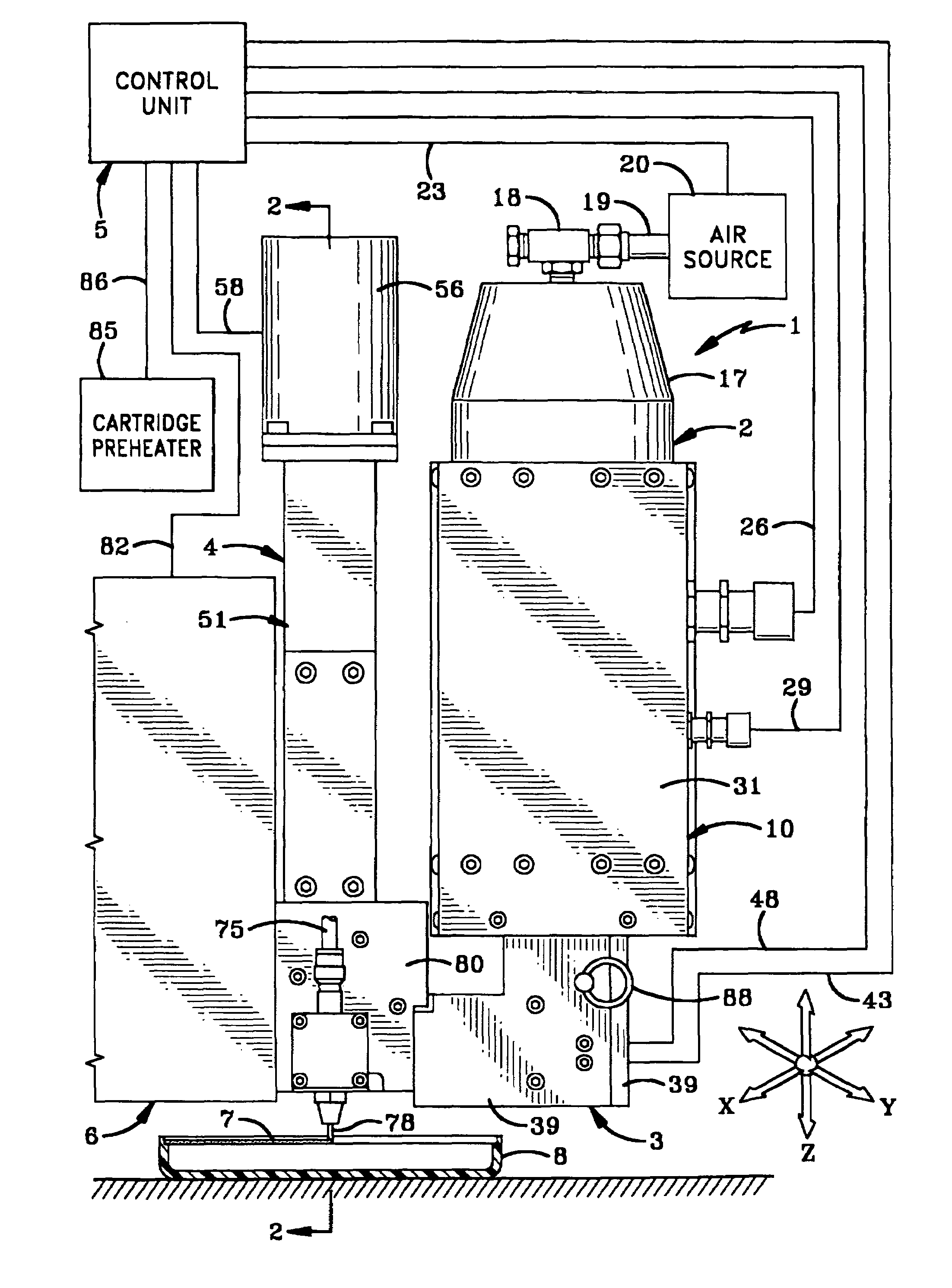
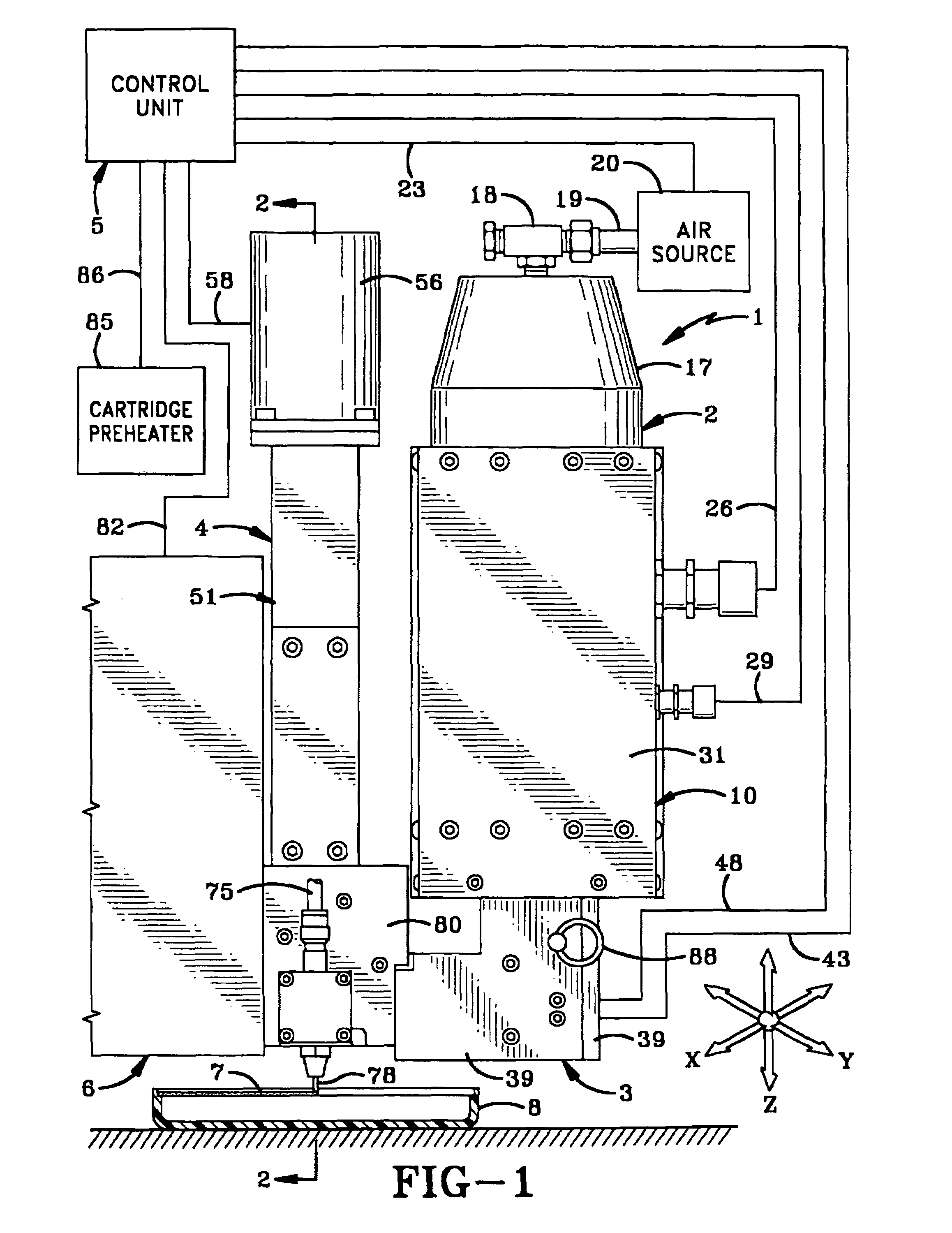
[0028]The apparatus of the present invention which is in the form of a compact dispensing unit is indicated generally at 1, and is shown particularly in FIGS. 1 and 7. Unit 1 includes as its main components an adhesive feed assembly 2, an inlet block 3, a positive displacement adhesive dispenser 4, and a control unit 5. Unit 1 preferably is mounted on a programmable, two or three-dimensional motion control unit 6 for depositing a dot, bead, or a strip of an adhesive 7 precisely on an object 8.

[0029]Adhesive feed assembly 2 is best shown in FIG. 7 and includes a housing indicated generally at 10, which contains a hollow sleeve 11 adapted to slidably receive a cartridge 13 therein, containing a supply of a hot-melt adhesive 15. An end cap 17 is mounted on the top of housing 10 and has a coupling 18 for receiving an air supply line 19 for supplying a positive air pressure to a piston 21 located within the interior of cartridge 13 for moving in the direction of arrow A, for discharging ...


PUM


Abstract

An apparatus and method for dispensing controlled precise amounts of a hot-melt adhesive. A positive displacement dispenser which is mounted on a programmable motion system is connected to a hot-melt cartridge feed assembly by an inlet block. The dispenser, feed assembly, and inlet block contain electric heaters and thermocouples for maintaining the adhesive at a desired elevated temperature. A computer control system regulates the temperature in the dispenser, feed assembly, and inlet block and controls a dispensing motor in the dispenser. A preheater heats an adhesive cartridge prior to placement in the feed assembly.

Description

BACKGROUND OF THE INVENTION[0001]1. Technical Field[0002]The invention relates to dispensing precise quantities of a hot-melt adhesive in exact locations on an object. In particular, the invention relates to a compact unit including an adhesive feed assembly and a positive displacement dispenser mounted closely together by an inlet block, which unit is mounted on a two or three-dimensional motion system and is connected to a control unit which maintains the temperature of the adhesive at critical levels as it moves through the unit and dispensed onto the object.[0003]2. Background Information[0004]The dispensing of extremely small amounts or shots of flowable materials at a precise location in a rapid and controlled manner presents a challenge to those in the dispensing art due to the viscosity of the materials and the extremely small amounts that must be precisely delivered at a precise location on an object. This is especially critical where the adhesive is a hot-melt moisture cur...

Claims


Application Information

Patent Timeline
Patent Type & Authority Patents(United States)
IPC IPC(8): B67D5/08B67D5/14F27B14/00B67D7/80B05C5/00B05C5/02B05C11/10B67D7/08B67D7/14B67D7/60
CPCB05C5/001B05C5/0216B05C11/1042B05C11/1015B05C11/10B67D7/60B67D7/80F27B14/00G01F11/00
Inventor RAINES, KEVIN M.GONZALEZ, HANK W.BLUMB, GEORGE E.
Owner GRACO INC
Why Eureka
Try Eureka