Imaging module for optical reader

a technology of optical readers and imaging modules, which is applied in the direction of instruments, sensing record carriers, visual presentations, etc., can solve the problems of imposing size requirements, time-consuming and expensive assembly of multiple circuit board arrangements of prior ar

Inactive Publication Date: 2007-11-20
HAND HELD PRODS
View PDF147 Cites 117 Cited by
  • Summary
  • Abstract
  • Description
  • Claims
  • Application Information

AI Technical Summary

Benefits of technology

[0022]The complementary components of the module are shaped so that the completed module exhibits a cubic rectangular form, thereby reducing the overall volume consumed by the entirety of optical components and at least the image sensing component of the reader in which the module is installed.
[0029]In addition to minimizing the size of the module, the module's configuration provides protection for internal components. The module's closed wall configuration provides a containment for internal components of the module, and substantially prevents outside objects from coming in contact with sensitive internal components of the module such as the module's image sensor and LEDs.

Problems solved by technology

Assembly of the multiple circuit board arrangement of the prior art is time consuming and expensive.
In addition adding to being difficult to assemble, the multiple circuit board design imposes size requirements on the optical reader housing in which the electrical components are to be integrated.

Method used


Image

  • Imaging module for optical reader
  • Imaging module for optical reader
  • Imaging module for optical reader

Examples


Embodiment Construction

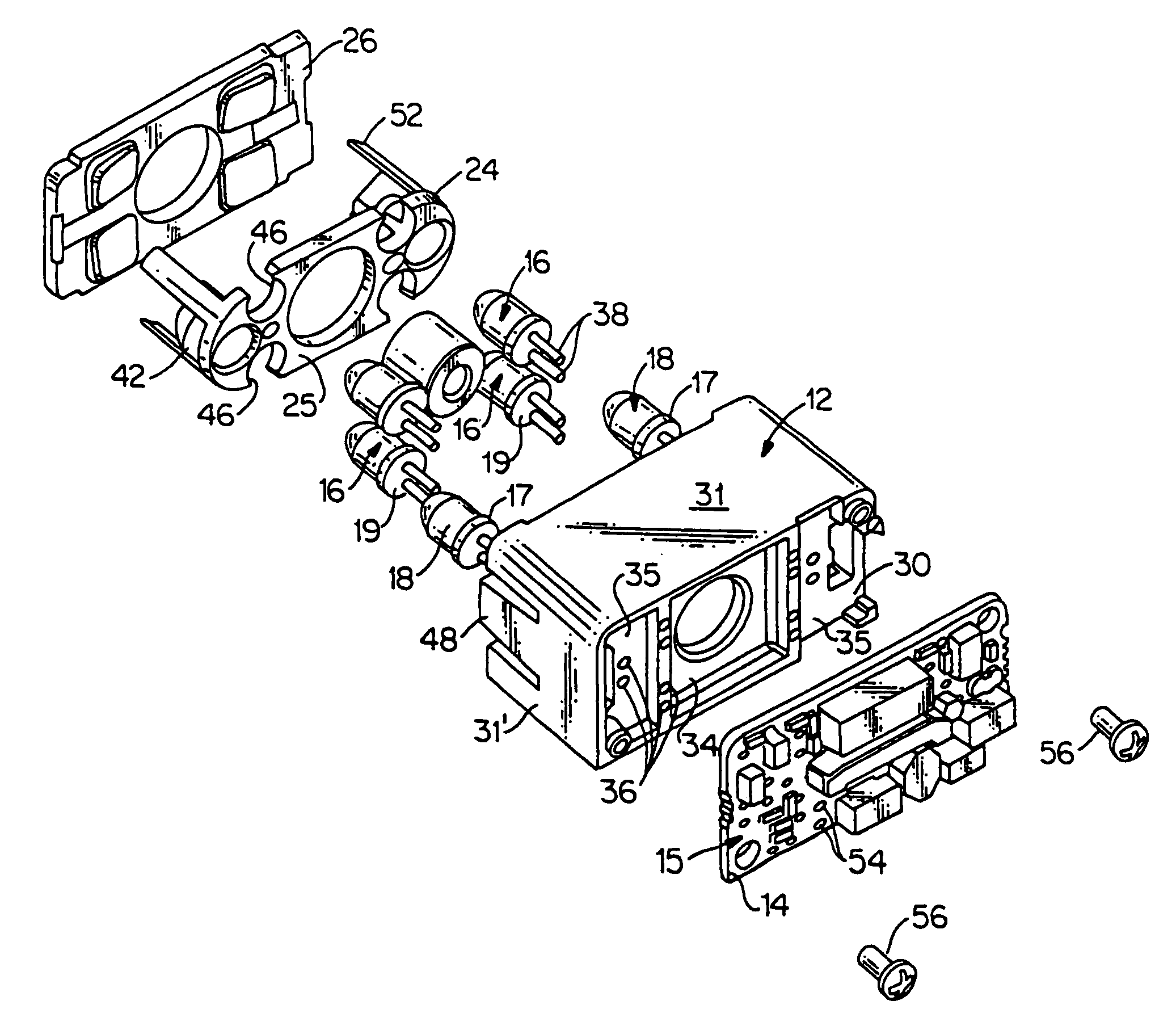
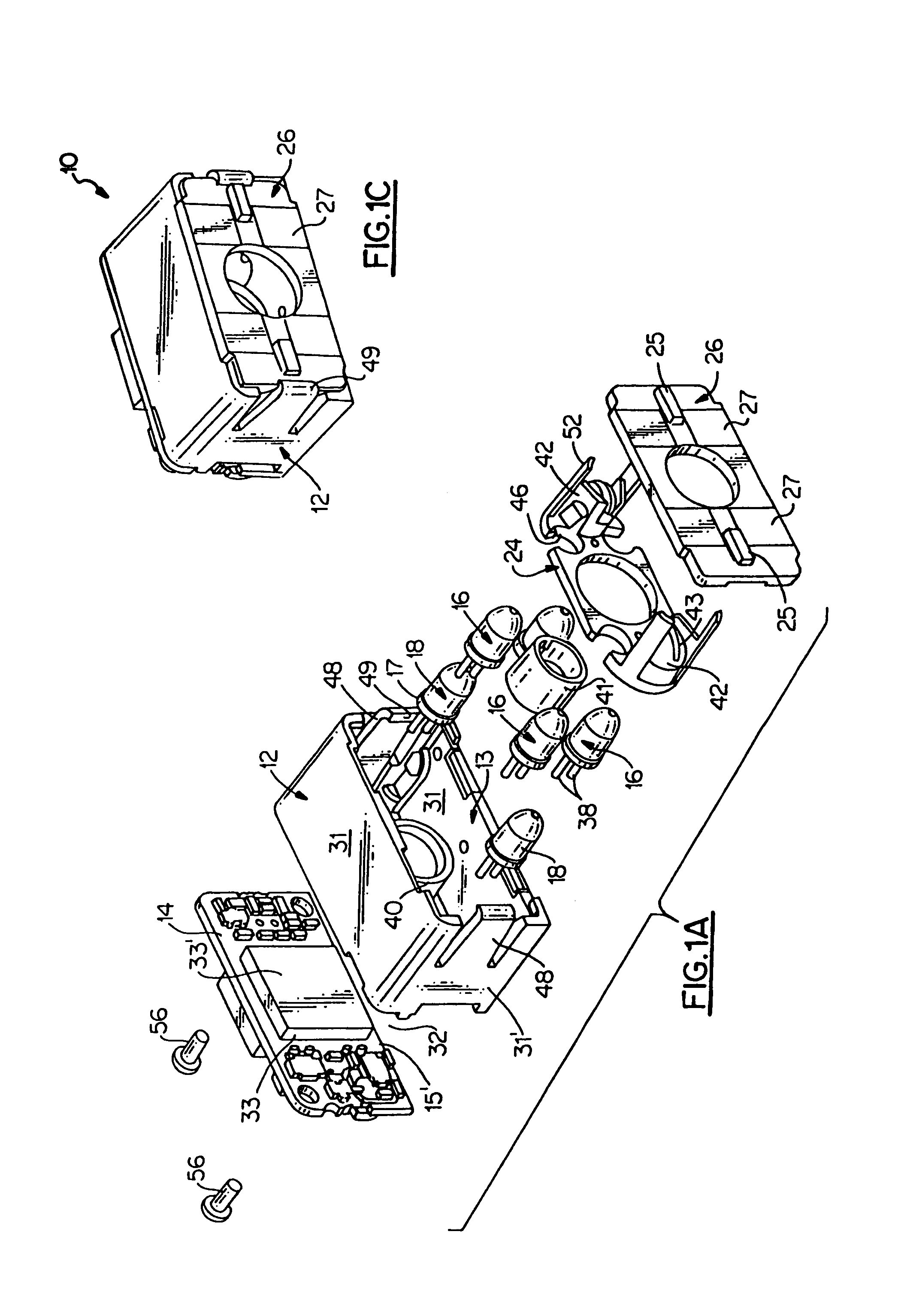
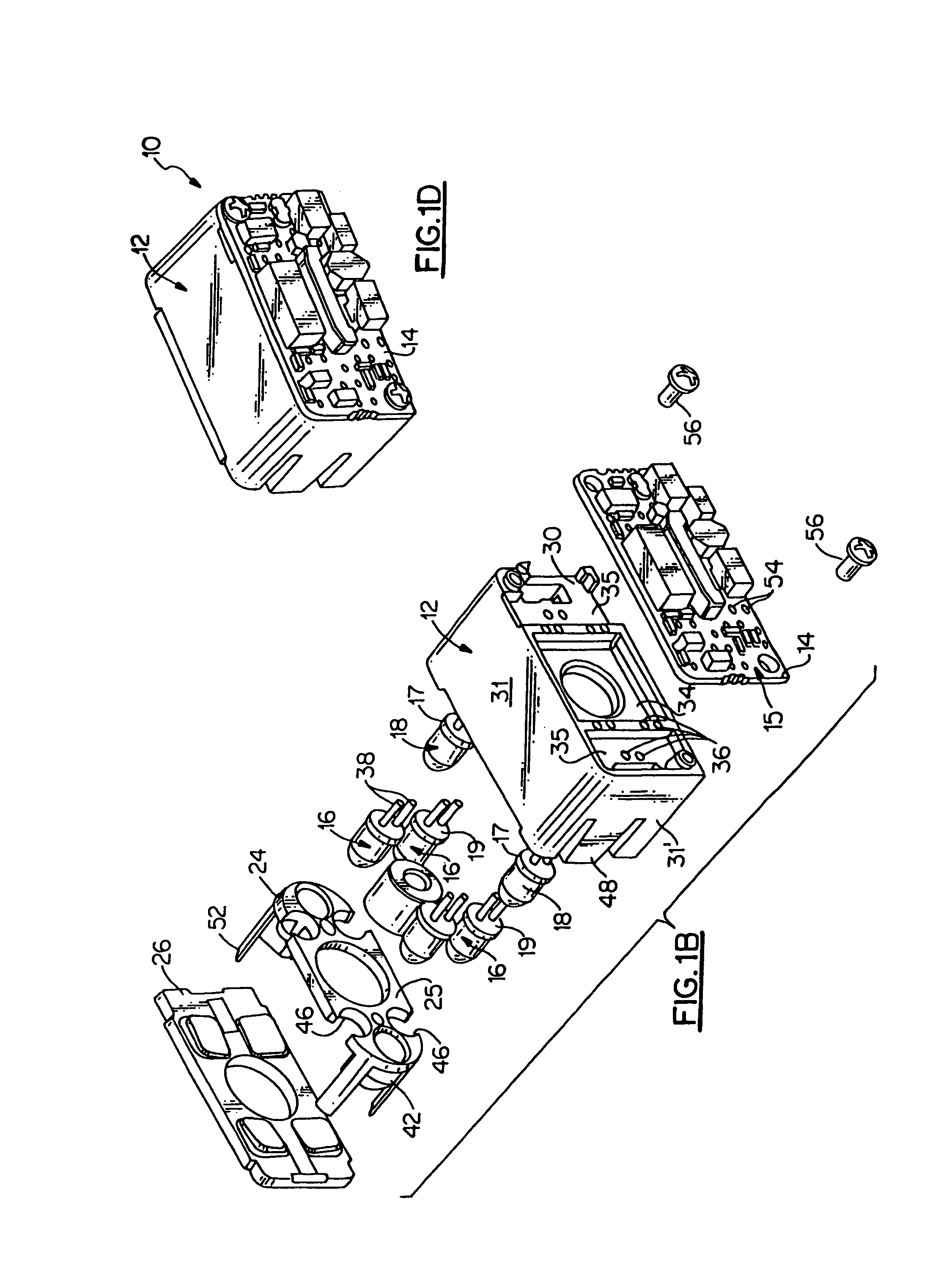
[0015]According to its major aspects and broadly stated the present invention is a module for packaging optical illumination, optical receive, and electrical signal processing components of an optical reader.

[0016]The module includes a frame which carries a printed circuit board, preferably a printed circuit board (PCB) and various optical components. In one embodiment, the frame includes a back plate having a retainer for receiving an optical lens barrel, and a recess for receiving and aligning an image sensor which is carried by the PCB. The frame may also include resilient fingers which enable the frame to receive certain optical components of the module in an adhesiveless snap-fitting arrangement.

[0017]According to a preferred assembly method for assembling the module, the PCB is first mounted onto the frame's back plate such that the image sensor of the PCB is received and aligned by the recess of the back plate. Next, illumination and aiming LEDs are soldered to the PCB to mou...


PUM


Abstract

The present invention relates to an apparatus packaging components of an optical reading device which may include illumination optical elements, receive optical elements, and signal processing elements. In one embodiment a single circuit board can carry multiple elements such as an image sensor together with illumination elements. In one embodiment, a control circuit can be provided that is coupled to a light source and an image sensor.

Description

CROSS REFERENCE TO RELATED APPLICATION[0001]This is a continuation application of U.S. Ser. No. 09 / 411,936, filed Oct. 4, 1999 and entitled Imaging Module for Optical Reader, the contents of which are relied upon and incorporated herein by reference in its entirety, and the benefit of priority under 35 U.S.C. 120 is hereby claimed.FIELD OF THE INVENTION[0002]The present invention relates to optical reading devices in general and in particular to an apparatus for elements of an optical reader.BACKGROUND OF THE INVENTION[0003]Currently available optical readers include illumination elements, electronic signal processing, image capture and decoding circuitry that are carried by more than one circuit board. For, example, shown in U.S. Pat. No. 5,780,834 is an optical reader having numerous circuit boards, including an LED board for carrying illumination LEDs, an “imaging board” carrying an image sensor and circuitry for processing signals generated from the image sensor, and a “mother b...

Claims


Application Information

Patent Timeline
Patent Type & Authority Patents(United States)
IPC IPC(8): G06K7/10G06K7/01H04N1/19
CPCG06K7/10722G06K7/10732G06K7/10742G06K7/109G06K7/1098G06K7/1417G06K7/10881G06K2207/1011
Inventor BARBER, CHARLES P.GERST, III, CARL W.HUNTER, VIVIAN L.MCCALL, MELVIN D.HAHN, BRUCE L.
Owner HAND HELD PRODS
Why Eureka
Try Eureka