Fault location using measurements of current and voltage from one end of a line

a technology of current and voltage measurement and fault location, which is applied in the direction of fault location, fault location by conductor type, instruments, etc., can solve the problems of relatively difficult to compensate for shunt capacitance effects by using these values, and difficult to obtain accurate pre-fault quantities. , to achieve the effect of facilitating the compensation of shunt capacitance and improving accuracy

Inactive Publication Date: 2007-11-20
HITACHI ENERGY SWITZERLAND AG
View PDF9 Cites 16 Cited by
  • Summary
  • Abstract
  • Description
  • Claims
  • Application Information

AI Technical Summary

Benefits of technology

[0007]In one aspect of the invention, a method comprising a new formulation of a one-end fault locator algorithm has been proposed. The uniform description of the transmission network in terms of symmetrical components as well as the generalized models of fault loops and faults have been applied. The resulting advantages include the algorithm can be used for locating faults in typical single and parallel transmission lines, and, in addition, fault location may also be carried out for both single and parallel lines with an extra link between the line ends. Another advantage is that a procedure for calculation of a distance to fault is in the form of a compact quadratic equation with the coefficients dependent on a fault type, acquired measurements and impedance data for the transmission network. Another advantage of the invention is that optimal estimation of the voltage drop across a fault path is applied, which has the result that the pre-fault currents in case of single phase-to-ground faults and phase-to-phase faults are no longer required.
[0008]In an embodiment, compensation for shunt capacitances is facilitated by means of the use of the notation of symmetrical components. The distributed long line model of the line has been applied for that. The compensation is performed individually for all the sequences. The currents for particular sequences are compensated for the shunt currents and then the fault loop compensated current is composed. In another embodiment improved accuracy has been obtained by means of an option to measure the source impedance at the remote end instead of using a representative value. The source impedance measured at the remote end may be considered as sent to the fault locator by using a simple communication means.
[0009]In another embodiment, a method for one end fault location for parallel lines to locate single phase-to-ground faults is described under a plurality of conditions. In another further embodiment a method is described for one end fault location with standard availability of the measured signals for ground faults including both single phase-to-ground faults and phase-to-phase-to-ground faults.
[0010]In another aspect of the invention, a fault locator device for carrying out the method of the invention is characterised by claim 18. Specific features of the inventive fault locator device are characterised by the appending claims.
[0011]In another aspect of the invention a computer program is described for carrying out the method according to the invention. In another aspect of the invention a computer program product comprising a computer program for carrying out the method of the invention is described. In another, further aspect of the invention a graphical user interface is described for displaying a distance to a fault from one end of a section of a power line.

Problems solved by technology

However, for certain fault conditions it is difficult to obtain accurate pre-fault quantities, such as pre-fault currents, in order to calculate an estimate for voltage drop across the fault path.
Also, a disadvantage of using phase voltages and currents and zero sequence components of currents is that it is relatively difficult using these values to compensate for shunt disadvantage of using phase voltages and currents and zero sequence components of currents is that it is relatively difficult using these values to compensate for shunt capacitance effects.
In addition, the fault locator method described is not suitable for single and parallel line sections which have an extra link across the ends of the sections.

Method used


Image

  • Fault location using measurements of current and voltage from one end of a line
  • Fault location using measurements of current and voltage from one end of a line
  • Fault location using measurements of current and voltage from one end of a line

Examples


Embodiment Construction

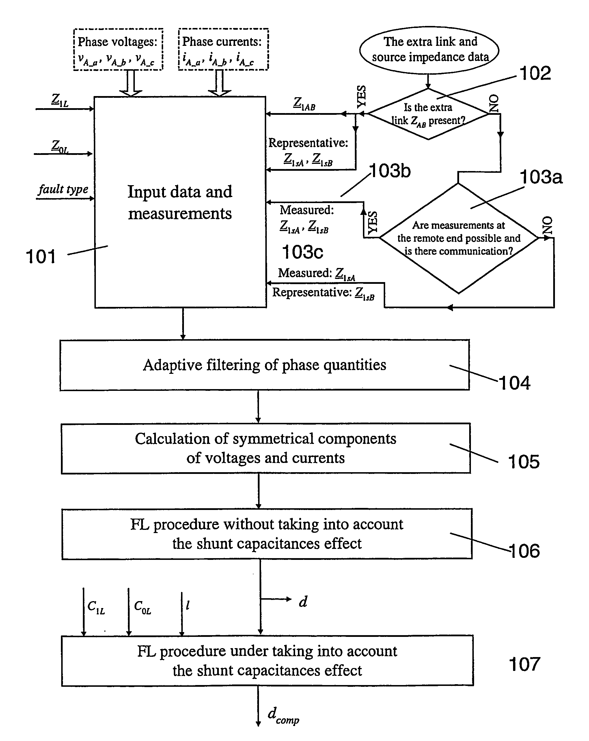
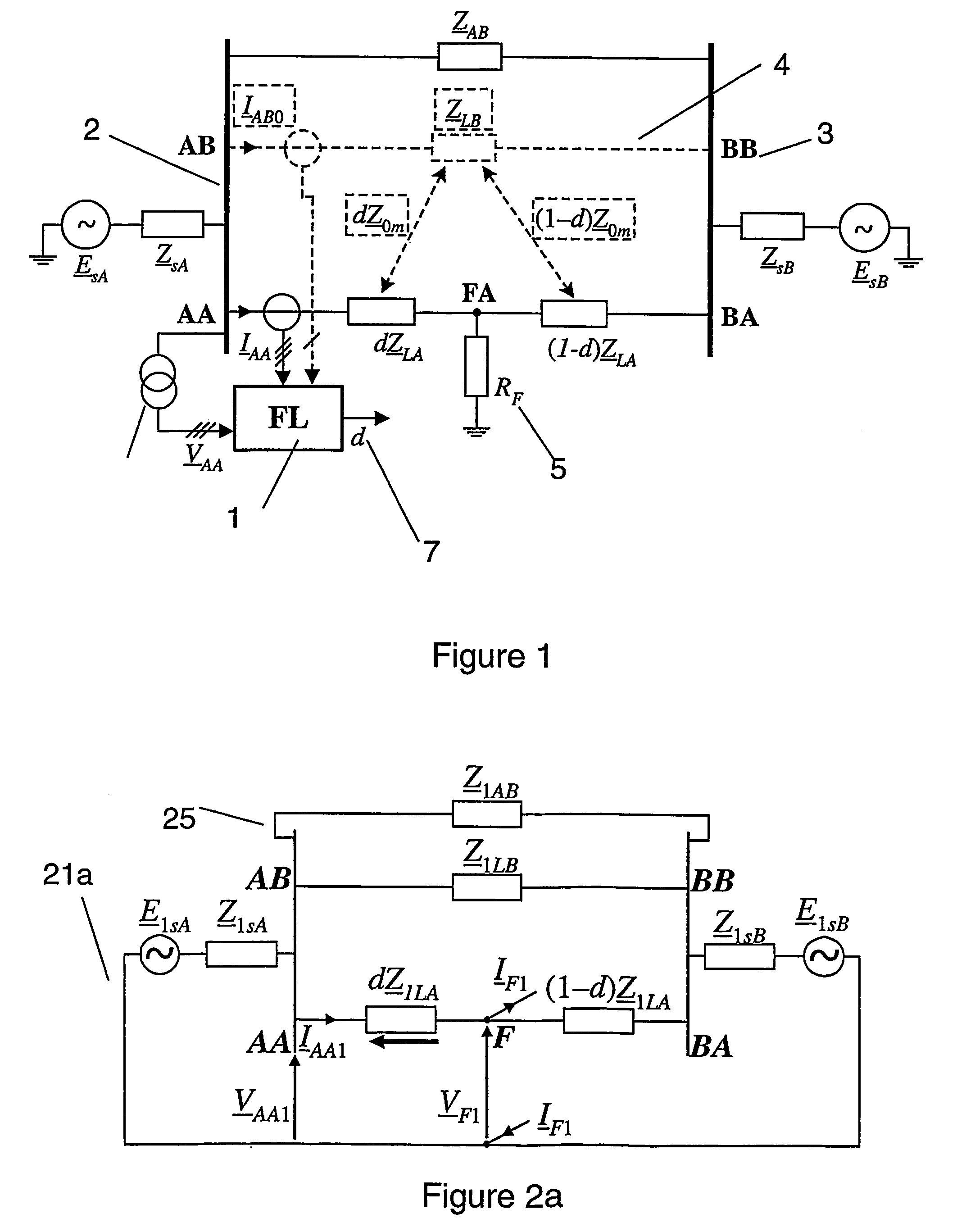
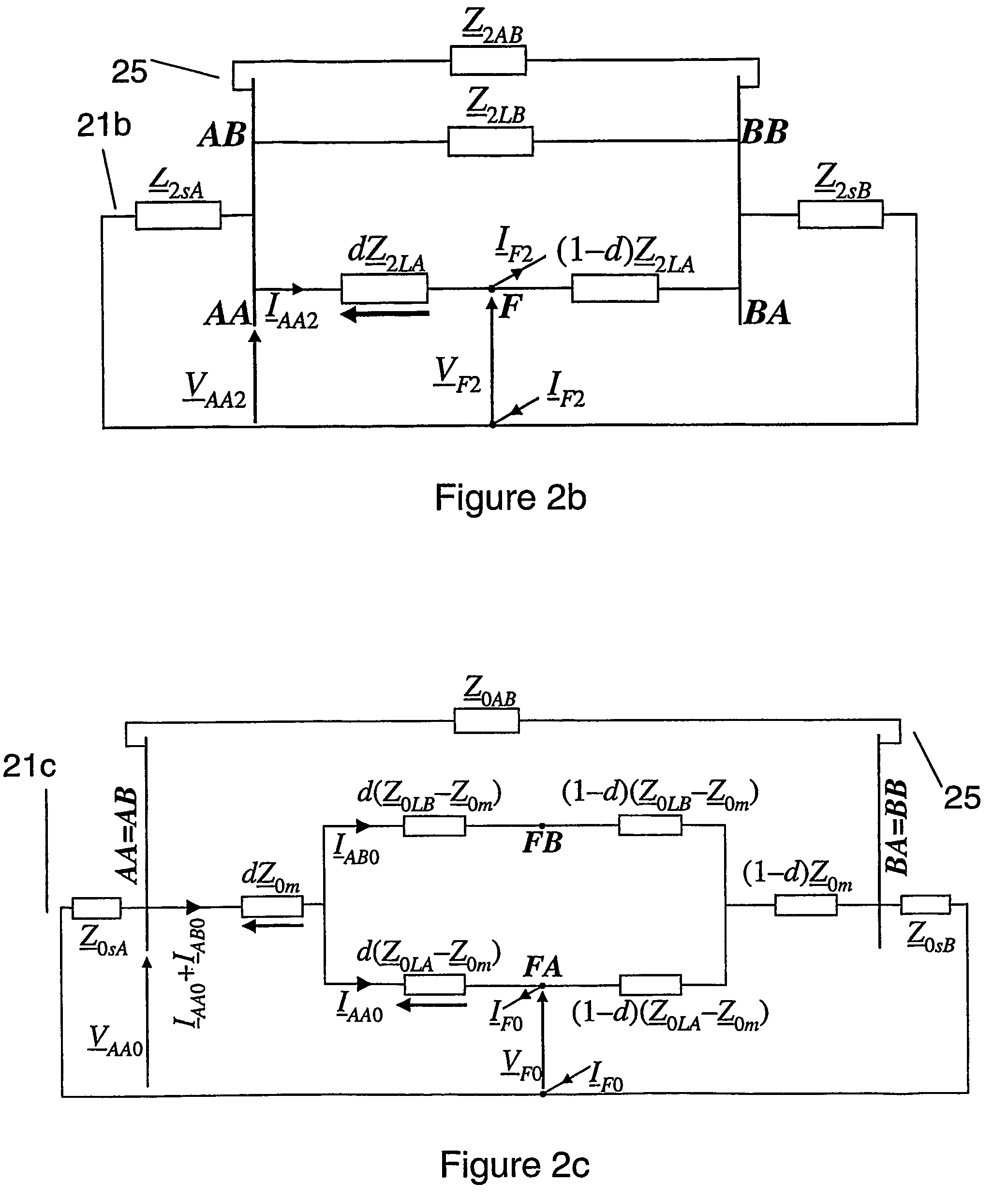
[0035]FIG. 1 presents a schematic diagram for one-end fault location applied for parallel lines and for a power transmission or distribution system with a single line. A fault locator 1 is positioned at one end 2 of a single line AA-BA 3 or parallel lines AA-BA, AB-BB, 4. A fault F is shown at FA with a corresponding fault resistance, 5, denoted as RF. A value for distance to the fault d from one end 2 determined and provided by the fault locator 1 is indicated with the reference number 7. Components such as parallel line AB-BB and quantities such as a parallel line value zero sequence current IAB0 shown with dotted lines are excluded when considering a single line case.

[0036]The fault locator 1 positioned at the first end 2, or ‘A’ end, is supplied with the following input signals:[0037]three-phase voltages (VAA) of the faulted line,[0038]three-phase voltages (IAA) of the faulted line,[0039]zero sequence current (IAB0) from the healthy parallel line (zero sequence is not present wh...


PUM


Abstract

A method to locate a fault from one end of a section of a power line utilizing measurements of current, voltage and angles between the phases at a first end of said section. Symmetrical components of currents are calculated for the current and voltage measurement at the first end. A value of impedance is calculated for an extra link between the terminals with the impedance for the positive sequence. A compensation is determined for the shunt capacitance. The zero-sequence current is determined from the healthy line of a section of parallel power lines. A distance to a fault is calculated for the parallel line section. The distance to the fault from the first end is calculated. The fault is located utilizing the calculate distances.

Description

CROSS-REFERENCE TO RELATED APPLICATIONS[0001]This application claims priority to Swedish patent application 0201911-5 filed 20 Jun. 2002 and is the national phase under 35 U.S.C. § 371 filed 18 Jun. 2003.TECHNICAL FIELD[0002]The present invention is concerned with a fault location technique for a section of a power transmission line utilizing measurements of current and voltage made at terminals located at one end of the section of the power line.BACKGROUND ART[0003]Several methods and approaches for fault location in high voltage power transmission systems, and power distribution systems, have been developed and employed. One approach has been to use voltage / current transducers located at terminals located at each of two ends of a section of the power line to be monitored. Inductive current transformers are used to provide a measurement of instantaneous current in a transmission line.[0004]U.S. Pat. No. 4,559,491 entitled Method and device for locating a fault point on a three-phas...

Claims


Application Information

Patent Timeline
Patent Type & Authority Patents(United States)
IPC IPC(8): G01R31/08H02H3/38H02H7/26
CPCG01R31/085H02H3/385H02H7/26G01R31/088
Inventor SAHA, MURARI MOHANIZYKOWSKI, JANROSOLOWSKI, EUGENIUSZ
Owner HITACHI ENERGY SWITZERLAND AG
Why Eureka
Try Eureka