Transmission output control circuit, and wireless device using the same

a control circuit and output technology, applied in the field of information communication devices, can solve problems such as difficult circuit downsizing, and achieve the effect of stable transmitting output control

Inactive Publication Date: 2007-11-20
PANASONIC CORP
View PDF19 Cites 55 Cited by
  • Summary
  • Abstract
  • Description
  • Claims
  • Application Information

AI Technical Summary

Benefits of technology

[0007]An object of the present invention is to provide a stable transmitting output control circuit, which can be used in a wide dynamic range necessary for detecting a transmitting output signal level, by using a diode built in a power amplifying apparatus as a detector.
[0018]In a word, by the detector using the diode which has been made into IC, when a dynamic range necessary for detecting the transmitting output signal level is small, the part of the transmitting output signal is taken by using the coupling capacitor. On the other hand, when a dynamic range is large, the part of the transmitting output signal whose isolation is kept enough can be taken stably by using the directional coupler. As a result, the transmitting output control circuit of the present invention can be used in a wide dynamic range. In addition, because the number of detectors for using can be reduced, the transmitting output control circuit can be downsized.

Problems solved by technology

Therefore, another detector 4b is needed at the outside of power amplifying apparatus 2 too, so that downsizing of the circuit is difficult.

Method used


Image

  • Transmission output control circuit, and wireless device using the same
  • Transmission output control circuit, and wireless device using the same
  • Transmission output control circuit, and wireless device using the same

Examples


first exemplary embodiment

[0030]The first exemplary embodiment of the present invention is demonstrated hereinafter with reference to the accompanying drawings.

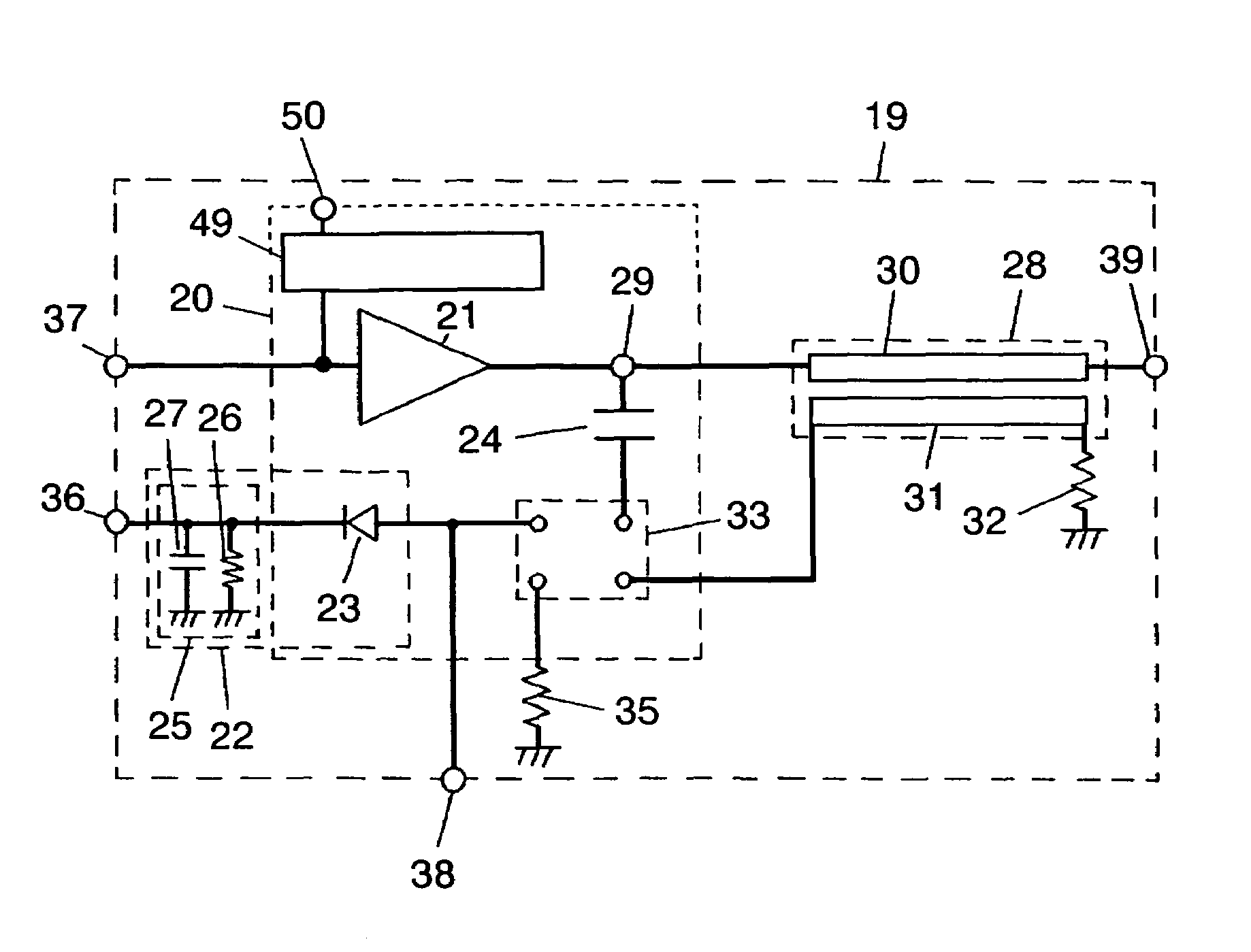
[0031]FIG. 1 is a block diagram showing a transmitting output control circuit of the present invention. As shown in FIG. 1, power amplifying apparatus 20 used in transmitting output control circuit 19 includes first diode 23 used in detector 22 and coupling capacitor 24 besides power amplifier 21. For example, in a case where a signal level, which is input into signal input terminal 37 of transmitting output control circuit 19, is controlled so as to be kept substantially constant, a level of an output signal output from amplifier output terminal 29 of power amplifier 21 is also substantially constant (approximately 15 dBm). Therefore, even when dynamic range necessary for detecting is small (e.g., 10 dB), it is available. In this case, a part of the transmitting output signal level is taken from coupling capacitor 24 coupled with amplifier output ter...

second exemplary embodiment

[0046]The second exemplary embodiment of the present invention is demonstrated hereinafter with reference to the accompanying drawings.

[0047]FIG. 7 is a perspective view of transmitting output control circuit 19 in accordance with the second exemplary embodiment of the present invention. FIG. 8 shows a plan view of surface layer 41 and dielectric layer 42. In these drawings, the elements similar to those shown in the first exemplary embodiment have the same reference marks, and the descriptions of those elements are omitted here.

[0048]In transmitting output control circuit 19 of FIGS. 7 and 8, power amplifying apparatus 20, first terminating resistor 32, second terminating resistor 35 and load resistor 26 of a smoothing circuit are mounted on surface layer 41 of multilayer board 40, and directional coupler 28 is integrated into dielectric layer 42.

[0049]Main line 30 of directional coupler 28 is coupled with amplifier output terminal 29 through via hole 45a, and sub line 31 is couple...

third exemplary embodiment

[0053]The third exemplary embodiment of the present invention is demonstrated hereinafter with reference to the accompanying drawings. FIG. 9 is a block diagram showing a transmitter of a wireless device using a transmitting power control circuit of the present invention. In these drawings, the elements similar to those shown in the first exemplary embodiment have the same reference marks, and the descriptions of those elements are omitted here.

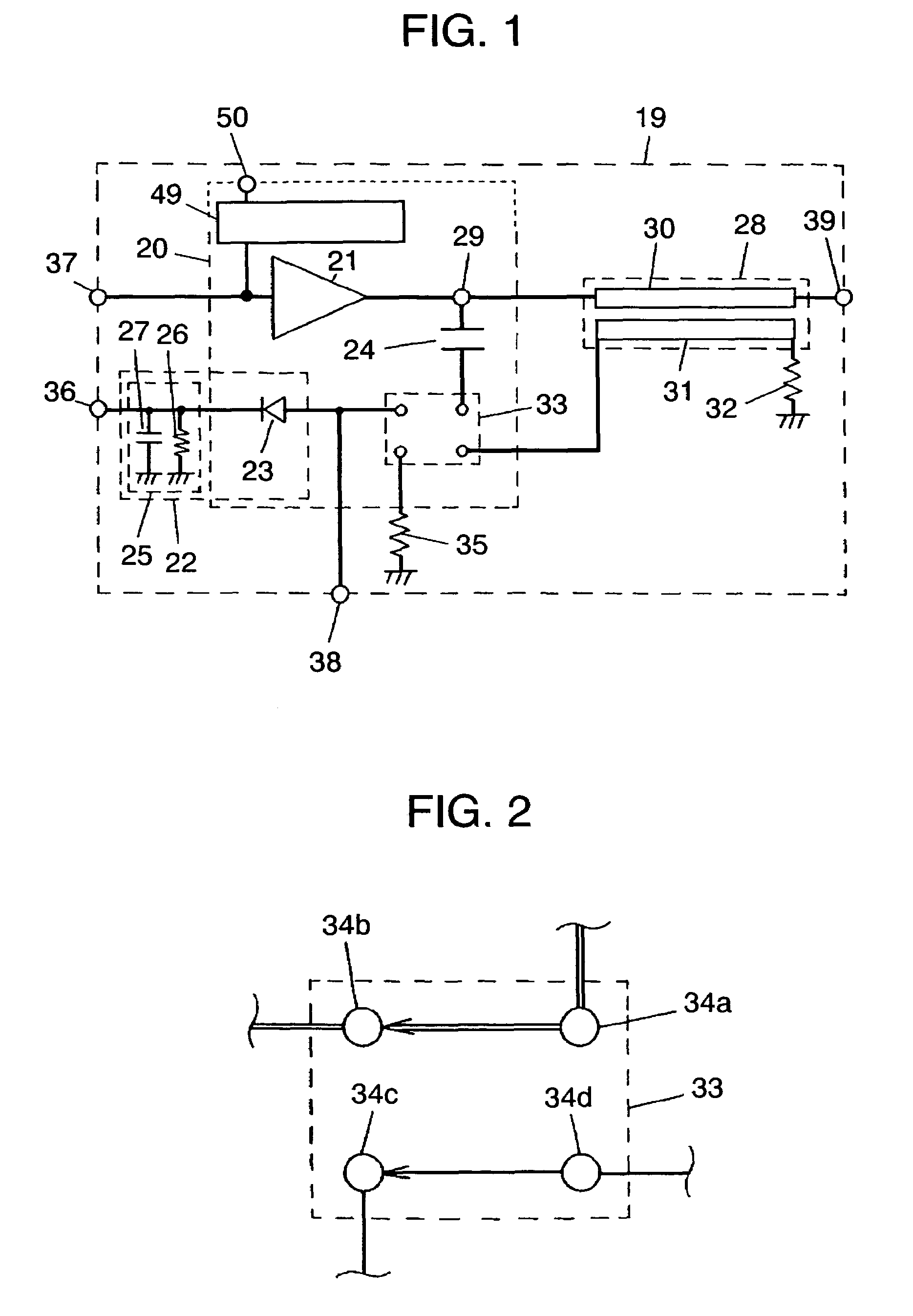
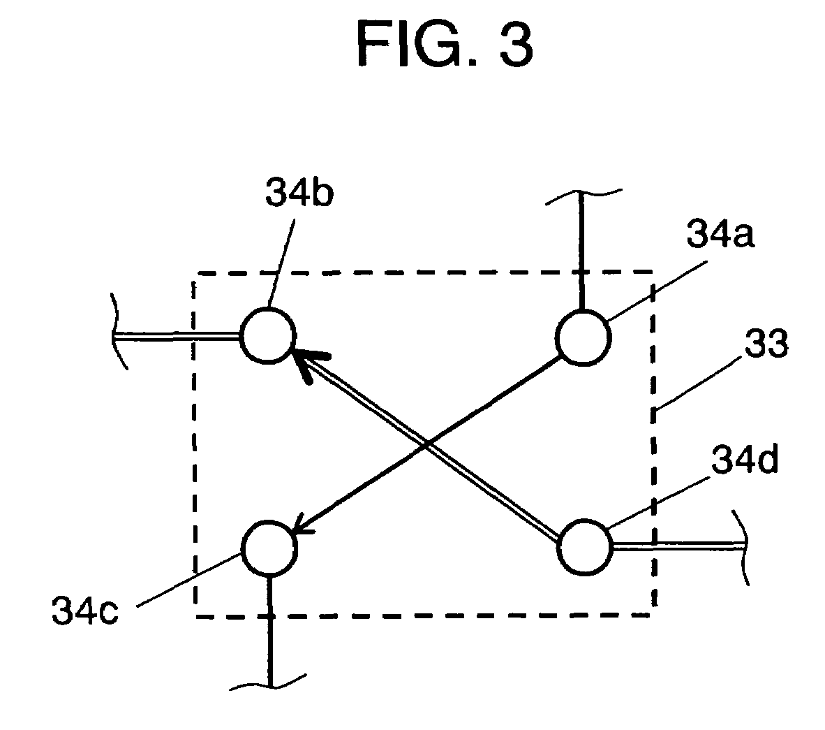
[0054]In FIG. 9, a part of a transmitting output signal level of power amplifying apparatus 20 is taken by coupling capacitor 24 and directional coupler 28. Switch 33 is switched so as to couple with coupling capacitor 24 or directional coupler 28 based on a dynamic range necessary for detecting a transmitting output signal level in the same manner as the first exemplary embodiment. The taken transmitting output signal level is changed into a smoothed detecting signal by smoothing capacitor 27 of smoothing circuit 25 in detector 22. This dete...


PUM


Abstract

According to a transmitting output control circuit, one end of a coupling capacitor and one end of main line of a directional coupler are coupled with an output terminal of a power amplifier. A switch for coupling the other end of the coupling capacitor and one end of a sub line of the directional coupler with an anode of a first diode or a second terminating resistor is formed in a power amplifying apparatus. Any one of the coupling capacitor and the directional coupler is coupled by switching the switch. By using this structure, the stable transmitting power control circuit, which can be used in a wide dynamic range necessary for detecting a transmitting output signal level, can be provided.

Description

[0001]This application is a U.S. National Phase Application of PCT International Application PCT / JP2005 / 009047.TECHNICAL FIELD[0002]The present invention relates to an information communication device in an information communication field and more particularly to a transmitting output control circuit for controlling a transmitting signal emitted from an antenna, and a wireless device using the same.BACKGROUND ART[0003]FIG. 10 is a block diagram showing a conventional transmitting output control circuit. Power amplifying apparatus 2 used in this transmitting output control circuit 1 includes diode 5 of detector 4a and coupling capacitor 6 besides power amplifier 3.[0004]When a dynamic range necessary for detecting a transmitting output signal level is small, detector 4a can be formed of diode 5 built in power amplifying apparatus 2, load resistor 8 used for outside smoothing circuit 7 and smoothing capacitor 9. On the other hand, when the dynamic range necessary for detecting the tra...

Claims


Application Information

Patent Timeline
Patent Type & Authority Patents(United States)
IPC IPC(8): H04B1/04H03G3/00H01Q11/12H03F1/06H03F1/30H03F3/24H03F3/60H03G3/30
CPCH03F1/0205H03F1/30H03F1/345H03F3/60H03G3/3042H03F3/24H04B1/04H03F2200/99
Inventor IWAMIYA, HIROKIOSUMI, YUJI
Owner PANASONIC CORP
Why Eureka
Try Eureka