Process for lapping ring and pinion gears

a technology of ring gear and pinion gear, which is applied in the direction of gear teeth, gear-teeth manufacturing apparatus, work transfer apparatus, etc., can solve the problems of difficult to obtain where the arrangement is, noise and vibration that can be transmitted into the interior of the vehicle, and the need to relocate/re-arrange other areas, often at significant cos

Active Publication Date: 2007-11-27
AMERICAN AXLE & MFG
View PDF16 Cites 8 Cited by
  • Summary
  • Abstract
  • Description
  • Claims
  • Application Information

AI Technical Summary

Problems solved by technology

As the input pinion can be driven at relatively high rotational speeds, relatively small variances in the shape of the teeth of the input pinion and / or the ring gear can generate noise and vibration that can be transmitted into the interior of the vehicle.
Such arrangements, however, may be difficult to obtain where the arrangement is being fitted into an existing production facility that is relatively full of other equipment.
In such cases, it may be necessary to relocate / re-arrange other areas (often times at significant cost) simply to obtain an area that is shaped to accommodate an arrangement that employs gantry-type loaders.
Yet another drawback concerns the cost of gantry-type loaders.
As will be appreciated, gantry-type loaders are relatively complex and sophisticated pieces of equipment.
Consequently, they can be relatively expensive to procure, operate and maintain.
Furthermore, as the bulk of the cost of a gantry-type loader is associated with its loading portion rather than its gantry portion, it is typically not cost-effective to employ gantry-type loaders in situations where production volumes are relatively low initially but expected to ramp up over the course of several years (to volumes that readily justify gantry-type loaders).
Consequently, while a gantry-type loader can be scaled to a variety of production volumes, it is frequently not possible to justify such automation at relatively low manufacturing volumes.

Method used


Image

  • Process for lapping ring and pinion gears
  • Process for lapping ring and pinion gears
  • Process for lapping ring and pinion gears

Examples


Embodiment Construction

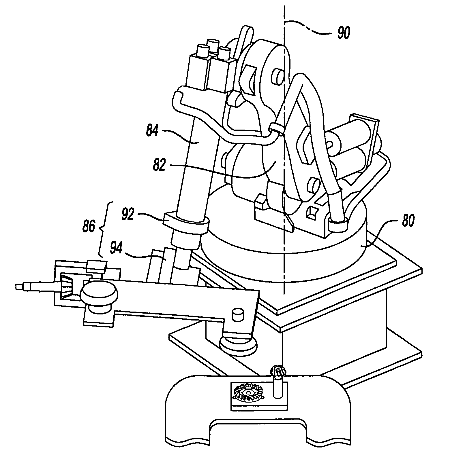
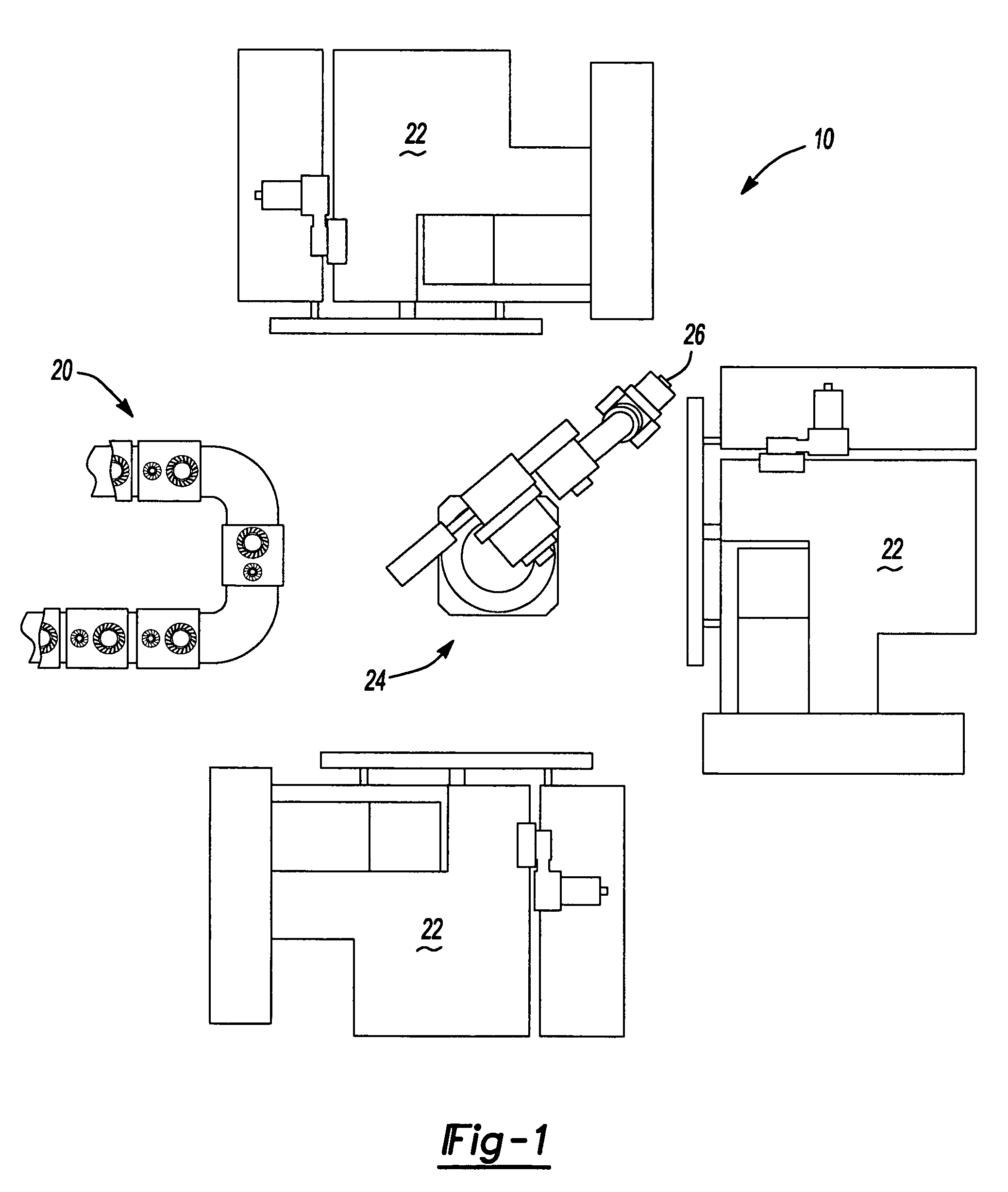
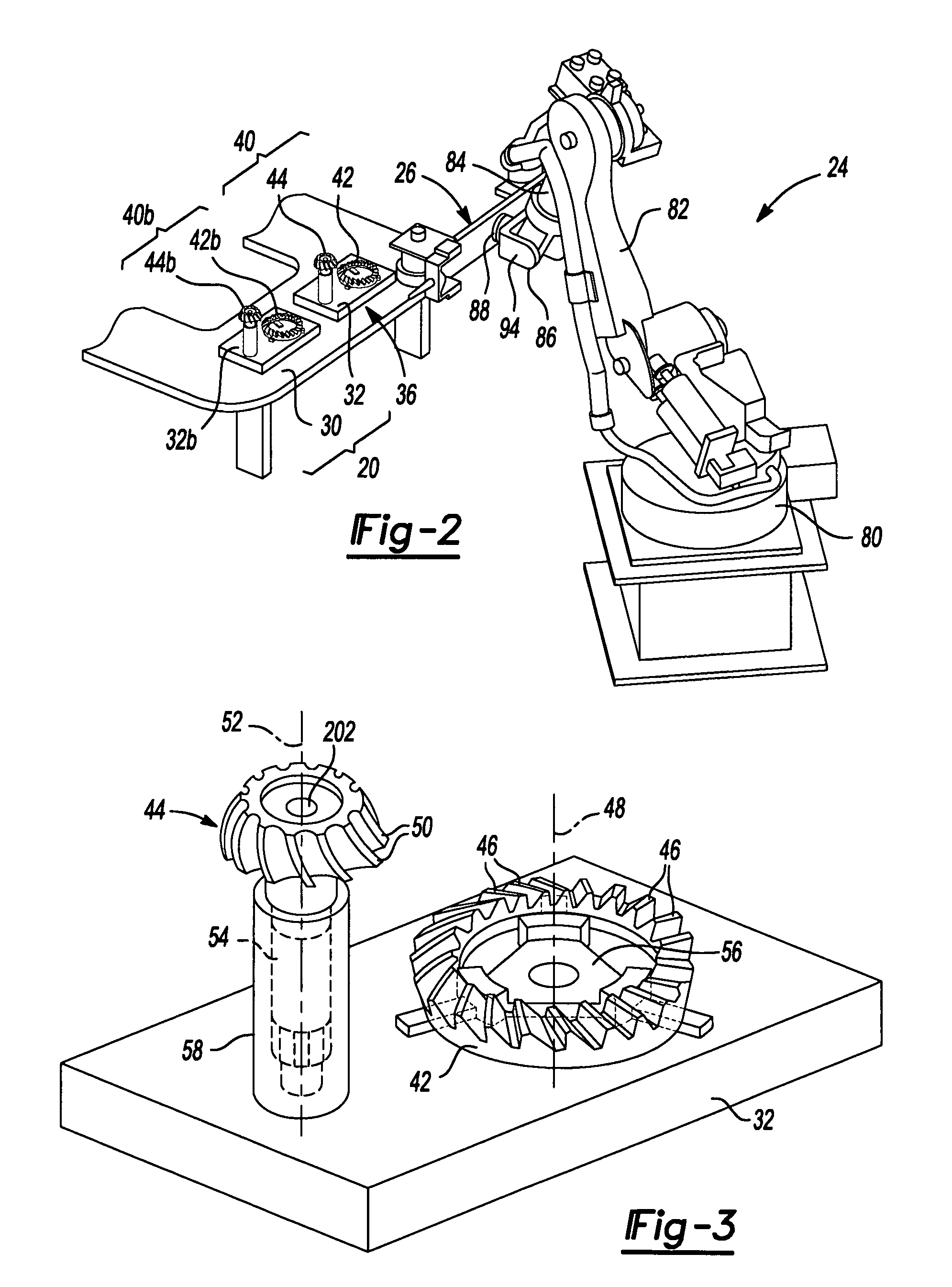
[0027]With reference to FIGS. 1 and 2 of the drawings, an exemplary facility for performing a lapping operation in accordance with the teachings of the present disclosure is generally indicated by reference numeral 10. The facility 10 can include a conveyance system 20, a plurality of lapping machine tools 22, a robot 24 and an end effector 26. The conveyance system 20 can include a conventionally constructed power-and-free type conveyor system 30 and a plurality of pallets 32. In so far as the present disclosure is concerned, the conveyance system 20 can be constructed in a conventional and well known manner and as such, need not be discussed in particular detail herein. Briefly, the conveyor system 30 can include a plurality of stations, including a loading station 36, and can be configured to transport the pallets 32 between the various stations in a desired manner. The power-and-free aspect of the conveyor system 30 can be employed to accumulate pallets 32 at one or more of the ...


PUM

PropertyMeasurementUnit
volumeaaaaaaaaaa
drive torqueaaaaaaaaaa
torqueaaaaaaaaaa

Abstract

A method for processing a gear set through a lapping operation that includes: providing a lapping machine tool having a first spindle and a second spindle, the second spindle being rotatable about an axis that is generally perpendicular to a rotational axis of the first spindle, the lapping machine tool having a loading zone for loading the first and second spindles; providing a robot with an end effector; loading a first gear set to a first end of the end effector, the first gear set having a ring gear and a pinion gear; moving the first end of the end effector into the loading zone; and loading the first gear set to the lapping machine tool without removing the end effector from the loading zone such that the ring gear is loaded onto the first spindle and the pinion gear is loaded onto the second spindle. An end effector is also provided.

Description

INTRODUCTION[0001]The present invention generally relates to manufacturing methods and tooling for the high-volume finishing of gearsets for automotive differentials and more particularly to manufacturing methods and tooling for processing a ring gear and pinion gear through a lapping operation.[0002]Modern automotive vehicles typically include a differential for controlling the transmission of drive torque to the driven wheels of the vehicle. The differential can include an input pinion and a ring gear. The input pinion can receive torque from the vehicle transmission or transfer case and can transmit the torque to the ring gear via the meshing teeth of the input pinion and ring gear. The ring gear can be coupled to a differential case, which can house a plurality of pinion gears and a pair of side gears that cooperate to differentiate drive torque between the two side gears.[0003]As the input pinion can be driven at relatively high rotational speeds, relatively small variances in ...

Claims


Application Information

Patent Timeline
Patent Type & Authority Patents(United States)
IPC IPC(8): B23Q7/04
CPCB23F17/008B23F23/04B23F19/025Y10T29/5124Y10S483/901Y10S483/902Y10S29/025Y10T29/49826Y10T483/1714Y10T29/49829Y10T409/10795Y10T483/16Y10T409/100954Y10T29/49828Y10T409/108586Y10T483/17Y10T409/109699
Inventor BICKERSTETH, DANIEL TGREENE, ROBERT GGEMBEL, II, KENNETH J
Owner AMERICAN AXLE & MFG
Why Eureka
Try Eureka