Vehicular lamp

a technology of vehicle lamps and lampshades, which is applied in the direction of fixed installation, lighting and heating apparatus, and support devices for lighting, etc., can solve the problems of not easy melting of snow and ice on the outer surface of the outer lens, and not a great deal of heat generation by light-emitting diodes

Inactive Publication Date: 2007-11-27
KOITO MFG CO LTD
View PDF6 Cites 23 Cited by
  • Summary
  • Abstract
  • Description
  • Claims
  • Application Information

AI Technical Summary

Benefits of technology

[0008]Accordingly, it is an object of the present invention to provide a vehicular lamp that has a heat radiation structure for preventing snow and ice on the outer lens of a vehicular lamp that uses light-emitting diodes as a light source.
[0010]In this structure of the present invention, the temperature of the outer lens can be kept high by the heat generated by the light-emitting diode and transferred to the cover member and then radiated to the outer lens. Accordingly, snow and ice on the outer lens are melted without using a heat source such as a heater.
[0011]In the present invention, a snow melting effect and the like is obtained by effectively using the heat from the light-emitting diode. Moreover, since the heat radiation structure of the present invention uses existing and known cover members (used as a necessary part), it is possible to lower the costs of vehicular lamps without making the structure of the vehicular lamp complicated.
[0012]In addition, in the present invention, the light-emitting diode can be mounted on a metal supporting member, and this supporting member is thermally connected to the cover member made of metal. In this structure, heat from the light-emitting diode is further effectively transferred from the supporting member to the cover member.
[0013]In addition, it can be structured so that a supporting member for attaching the lamp unit to the lamp body serves also as a cover member. With this structure, it is possible to further effectively reduce the number of parts.
[0014]In order to further improve the radiation effect of the heat to the outer lens, radiation fins that protrude toward the outer lens on the cover member can be provided.

Problems solved by technology

However, when the light-emitting diode is used as a light source, there is not much temperature increase by the radiation of light to the outer lens, and snow and ice on the outer surface of the outer lens do not easily melt.
More specifically, in a vehicular lamp with an incandescent light bulb, it is possible to melt the snow by the heat of the light ray transferred to the outer lens; however, light-emitting diodes do not produce heat in great deal.

Method used


Image

  • Vehicular lamp
  • Vehicular lamp
  • Vehicular lamp

Examples


Embodiment Construction

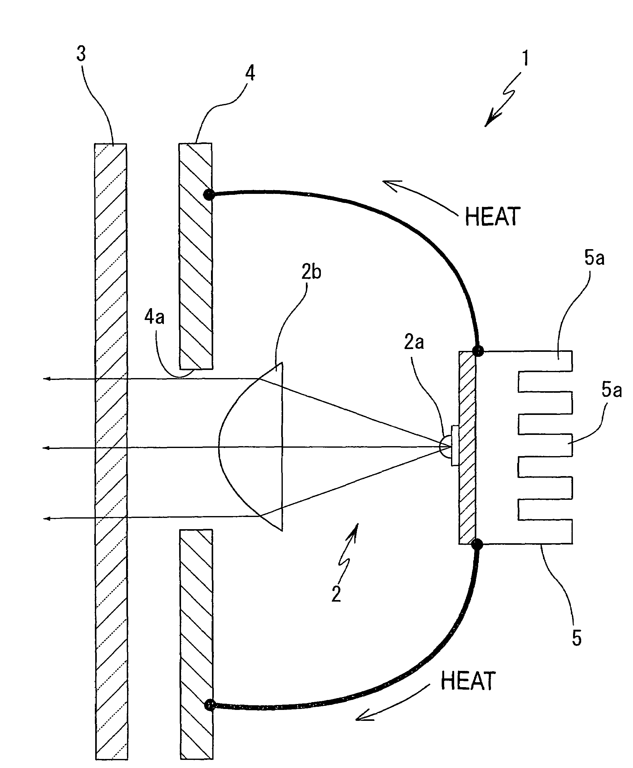
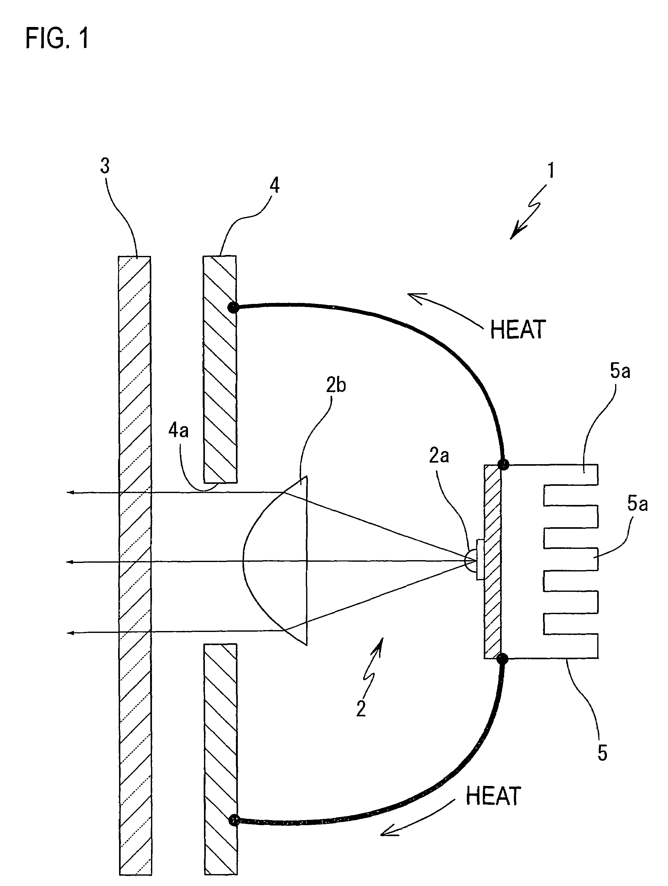
[0020]In the present invention, a vehicular lamp that uses a light-emitting diode as its light source melts the snow and ice on the outer lens by actively using the heat generated by the light-emitting diode, thus preventing the decrease in the illumination performance of the lamp in the winter season and in the cold regions.

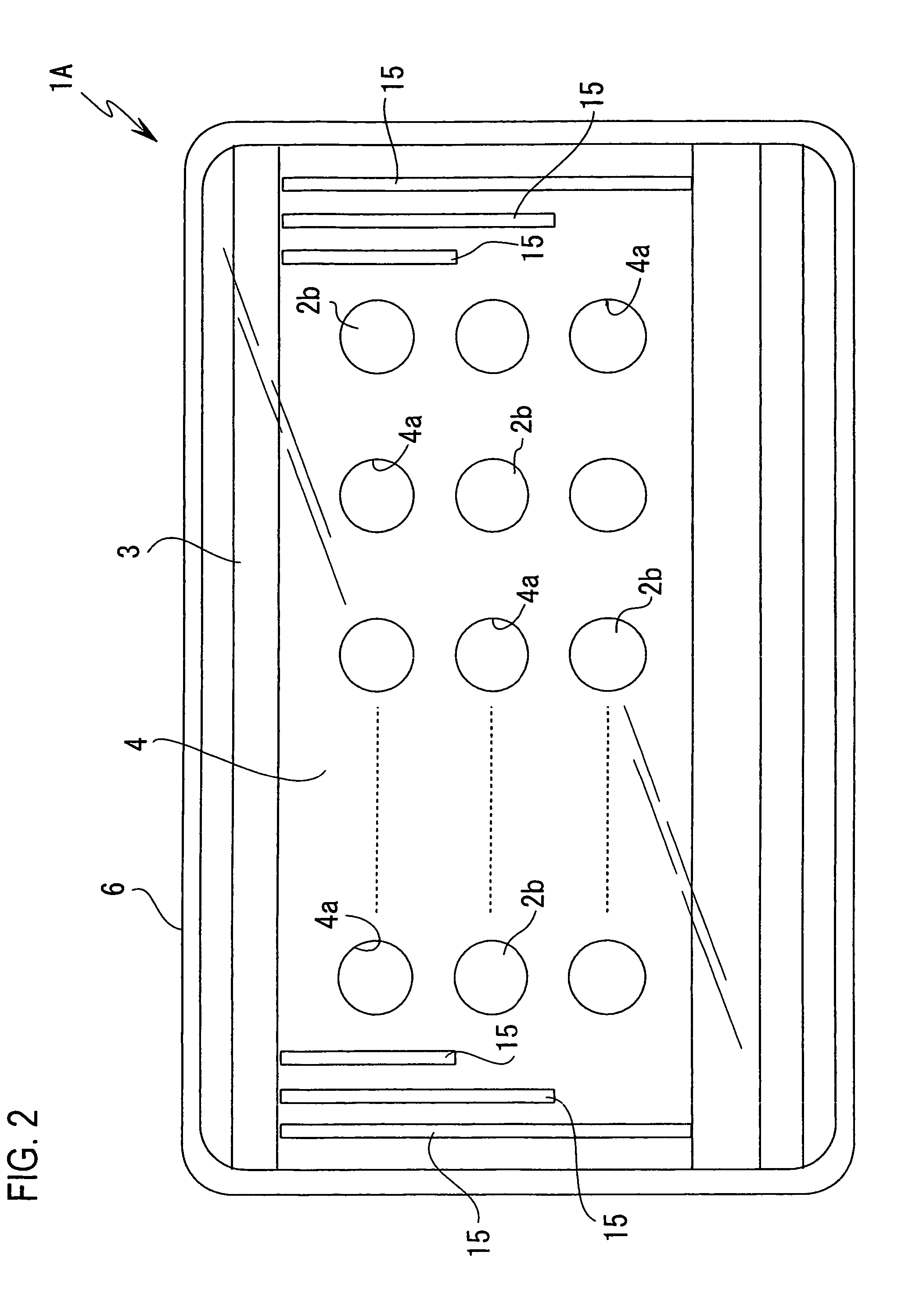
[0021]As seen from FIG. 1, the vehicular lamp 1 of the present invention includes a lamp unit 2, which uses a light-emitting diode 2a, and a cover member 4, which is positioned near the inside surface of the outer lens 3 installed in front of that lamp unit 2 (the direction in which light is radiated (left side in FIG. 1) is defined as the “front”).

[0022]In this lamp unit 2, light directly emitted from the light-emitting diode 2a passes, through a lamp unit lens 2b and goes through a translucent hole 4a of the cover member 4; and then the light is transmitted through the outer lens 3 and radiated forward. The structure of the lamp unit 2 is not limited to the on...


PUM


Abstract

A vehicular lamp 1 including a lamp unit 2, in which a light-emitting diode 2a is used as the light source, and a cover member 4, which is provided between the lamp unit 2 and an outer lens 3 of the lamp and located near the inside surface of the outer lens 3 so as to cover the lamp unit 2 except its light-emitting region. The cover member 4 is formed of a material that has good heat conductivity, and heat generated by the light-emitting diode 2a is transferred to the cover member 4 and to the outer lens 3, thus heating the outer lens.

Description

BACKGROUND OF THE INVENTION[0001]1. Field of the Invention[0002]The present invention relates to a vehicular lamp and more particularly to a vehicular lamp that uses a light-emitting diode as its light source and as a means for melting snow and ice on the outer lens.[0003]2. Description of the Related Art[0004]In one type of the known vehicular lamps, a plurality of lamp units, each comprising, among others, a lens and a reflector and having a light-emitting diode (LED) used as its light source, are installed in the lamp body. A desired light distribution is obtained by combining a direct light emitting type lamp unit and a reflective light emitting type lamp unit.[0005]Regarding the heat caused by lighting up the light-emitting diode, a heat sink or the like is used so that the generated heat is dissipated to the outside of the lamp chamber.[0006]However, when the light-emitting diode is used as a light source, there is not much temperature increase by the radiation of light to the...

Claims


Application Information

Patent Timeline
Patent Type & Authority Patents(United States)
IPC IPC(8): H01L27/00F21W107/00
CPCB60Q1/0005B60Q1/04F21S48/1154F21S48/1159F21S48/25F21S48/328F21V29/763F21V29/004F21V29/71F21V29/74F21V29/75F21S48/335F21Y2101/02Y10S362/80F21Y2115/10F21S41/143F21S41/148F21S41/153F21S43/50F21S45/33F21S45/48F21S45/60B60Q1/00B60Q1/02
Inventor OSHIO, HIROHIKOMOCHIZUKI, MITSUYUKI
Owner KOITO MFG CO LTD
Why Eureka
Try Eureka