Stator vane stage actuated by an automatically-centering rotary actuator ring

a technology of rotary actuator and actuator ring, which is applied in the direction of machines/engines, mechanical apparatus, liquid fuel engines, etc., can solve the problems of simple and fast assembly and adjustment, and achieve the effect of improving the control of the position of the drive ring, simple and fast assembly and adjustment, and ensuring the initial quality of centering

Active Publication Date: 2007-11-27
SN DETUDE & DE CONSTR DE MOTEURS DAVIATION S N E C M A
View PDF8 Cites 14 Cited by
  • Summary
  • Abstract
  • Description
  • Claims
  • Application Information

AI Technical Summary

Benefits of technology

[0008]The structure of the invention makes it possible to obtain an actuator ring of low weight that is accurately coaxial and does not have any operating clearance for expansion. In addition, assembly and adjustment are very simple and fast.
[0009]The system of the invention guarantees the initial quality of centering on a permanent basis, regardless of temperature and regardless of the materials used for the actuator ring and the casing. Control over the position of the drive ring is also improved during all stages of control. The risks of the actuator ring warping that used to be due to non-uniformity in the transmission of control forces are greatly reduced.
[0012]Compared with the system described in the above-mentioned US patent, it should be observed that the weight and the dimensions of the drive ring are greatly reduced, since the inner ring of the system described in that patent is omitted.

Problems solved by technology

In addition, assembly and adjustment are very simple and fast.

Method used


Image

  • Stator vane stage actuated by an automatically-centering rotary actuator ring
  • Stator vane stage actuated by an automatically-centering rotary actuator ring
  • Stator vane stage actuated by an automatically-centering rotary actuator ring

Examples


Embodiment Construction

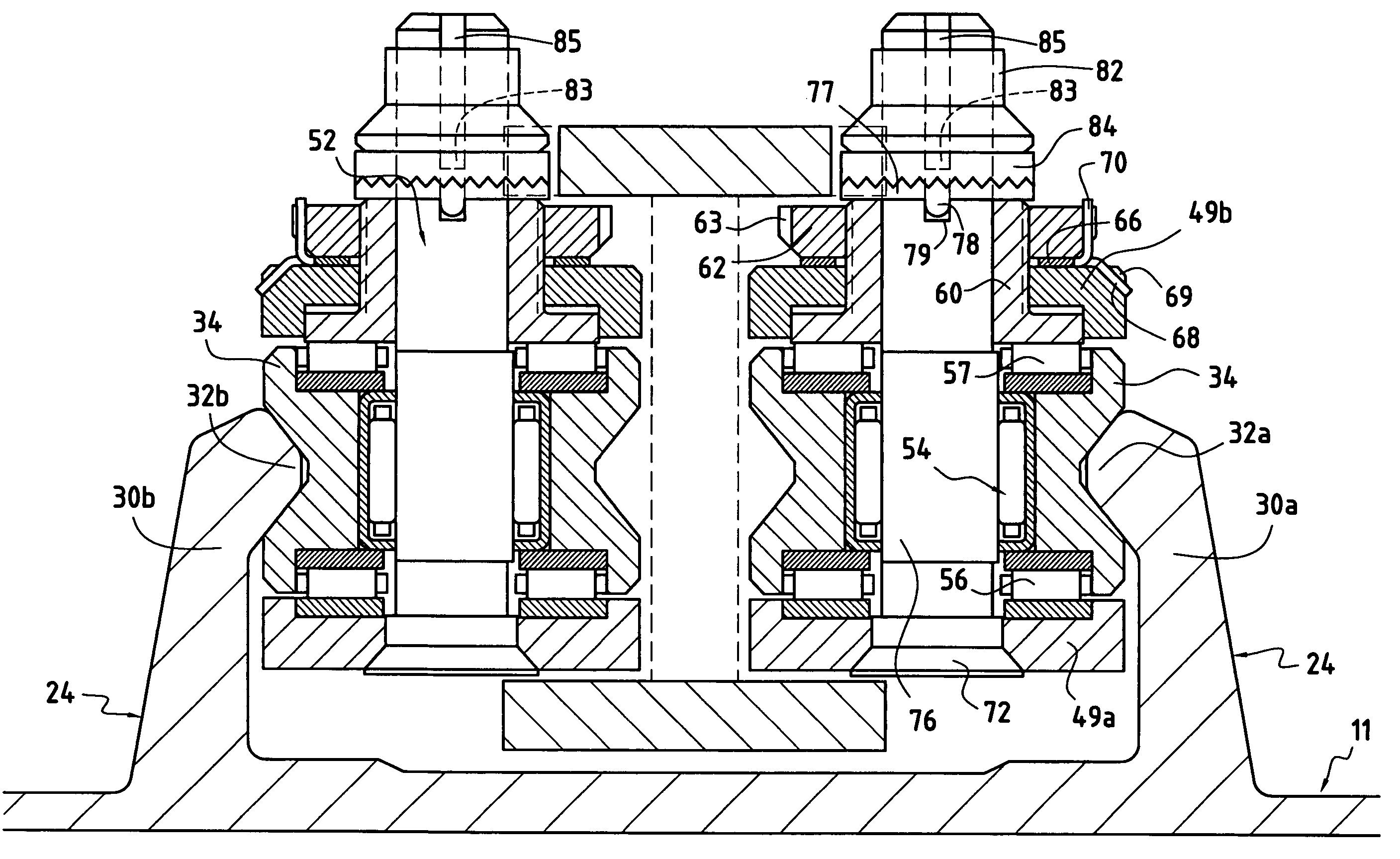
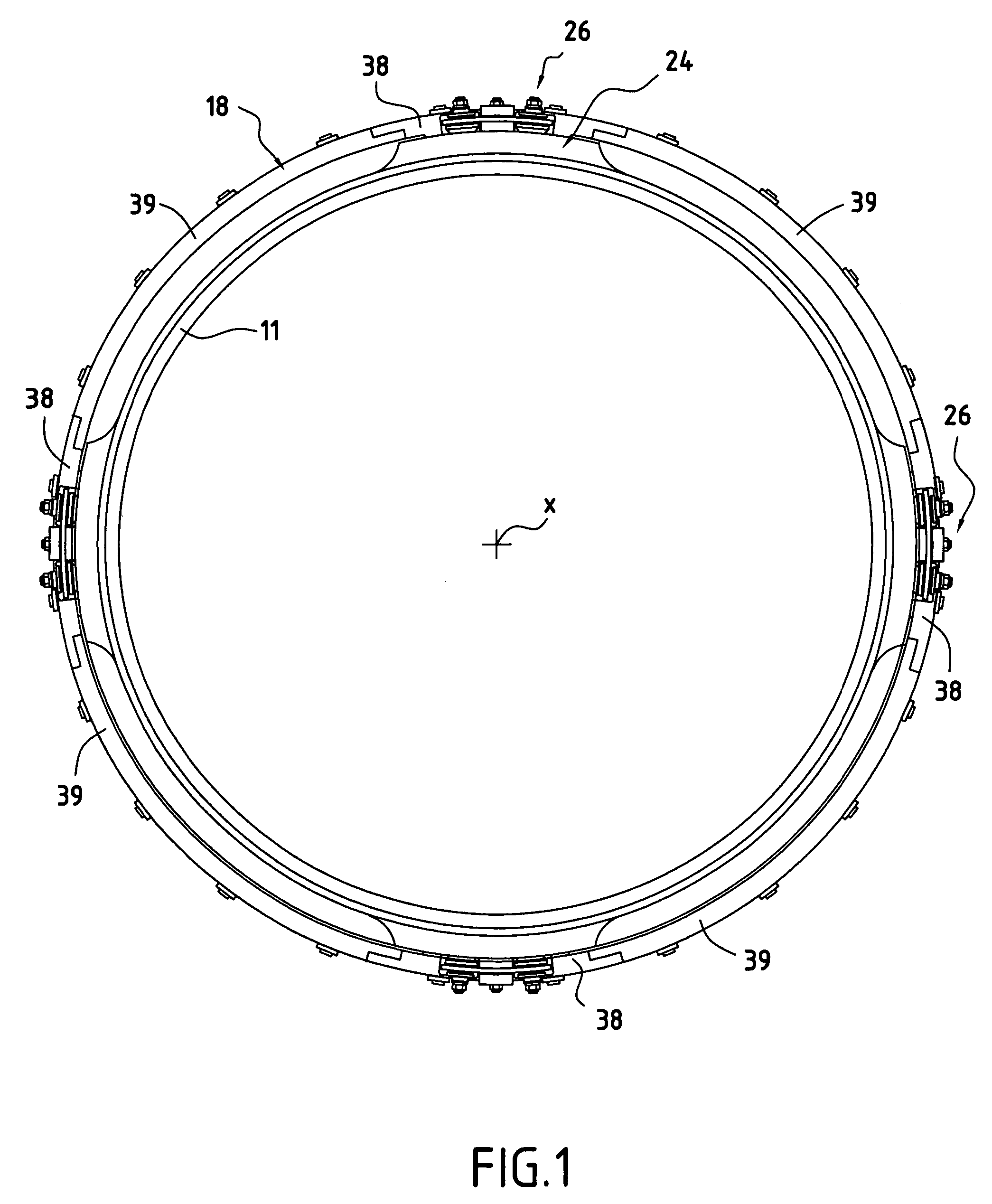
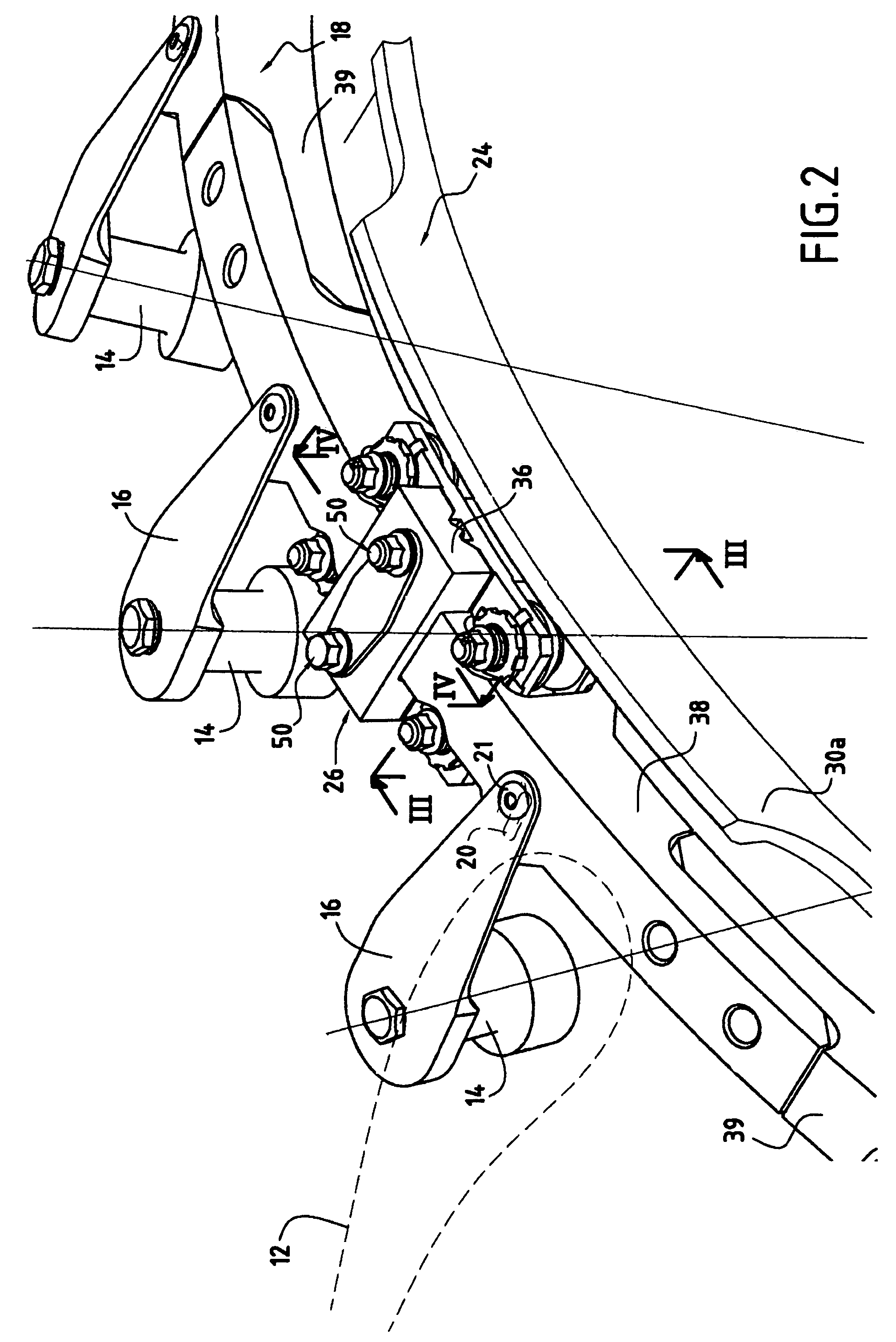
[0026]With reference more particularly to FIGS. 1 to 4, there can be seen the casing 11 of a turbomachine of axis X, which casing houses variable-pitch stator vanes 12, one of which is visible in FIG. 2. Each vane has a pivot 14 projecting from the casing and connected via a crank 16 to an actuator ring 18 outside the casing. The radial crank-drive holes 20 formed in the actuator ring and having tenons 21 engaged therein that are secured to the ends of the cranks are oblong since said actuator ring moves in rotation only. It will be understood that turning the actuator ring circumferentially causes all of the vanes 12 to pivot simultaneously inside the casing by the same amount. Thus, when the invention is applied to an airplane jet engine, the orientation of the vanes can be adjusted as a function of flying conditions. The main object of the invention is to provide very good centering of the actuator ring 18 with very small operating clearance, said centering not being disturbed by...


PUM


Abstract

A variable pitch stator vane stage, said vanes being moved by an automatically-centered rotary actuator ring. The casing carries a stationary coaxial annular rail projecting from its outside surface, and circumferentially spaced apart moving equipments are provided that are constrained to move along said rail, each moving equipment being coupled to the actuator ring via a radial guide arrangement.

Description

[0001]The invention relates to a turbomachine having a stator that includes at least one variable-pitch stator vane stage arranged in a casing, said vanes being moved by a rotary actuator ring located outside the casing and carried by the casing. The invention relates to an improvement to this type of actuator ring making it possible in particular to center the actuator ring automatically under all circumstances with very small operating clearance. The invention applies in particular to the field of airplane jet engines and more particularly to a compressor included in such a jet engine.BACKGROUND OF THE INVENTION[0002]In a turbomachine of the kind specified above, a compressor stator is fitted with at least one stator vane stage that is of variable pitch, i.e. the position of the vanes in the flow section is adjustable. More precisely, the angle of attack of the vanes is controlled as a function of operating conditions by a servo-control system which causes a rotary actuator ring o...

Claims


Application Information

Patent Timeline
Patent Type & Authority Patents(United States)
IPC IPC(8): F04D29/56
CPCF04D29/563F01D17/162F05D2230/64F05D2250/90Y02T50/60
Inventor BOURU, MICHEL ANDRE
Owner SN DETUDE & DE CONSTR DE MOTEURS DAVIATION S N E C M A
Why Eureka
Try Eureka