

Method of detecting an arc in a glow-discharge device and apparatus for controlling a high-frequency arc discharge
a technology of glow-discharge device and arc discharge, which is applied in the direction of plasma technique, vacuum evaporation coating, coating, etc., can solve the problems of damage to samples and the inability to detect arc discharg
- Summary
- Abstract
- Description
- Claims
- Application Information
AI Technical Summary
Benefits of technology
Problems solved by technology
Method used
Image

Examples
first embodiment
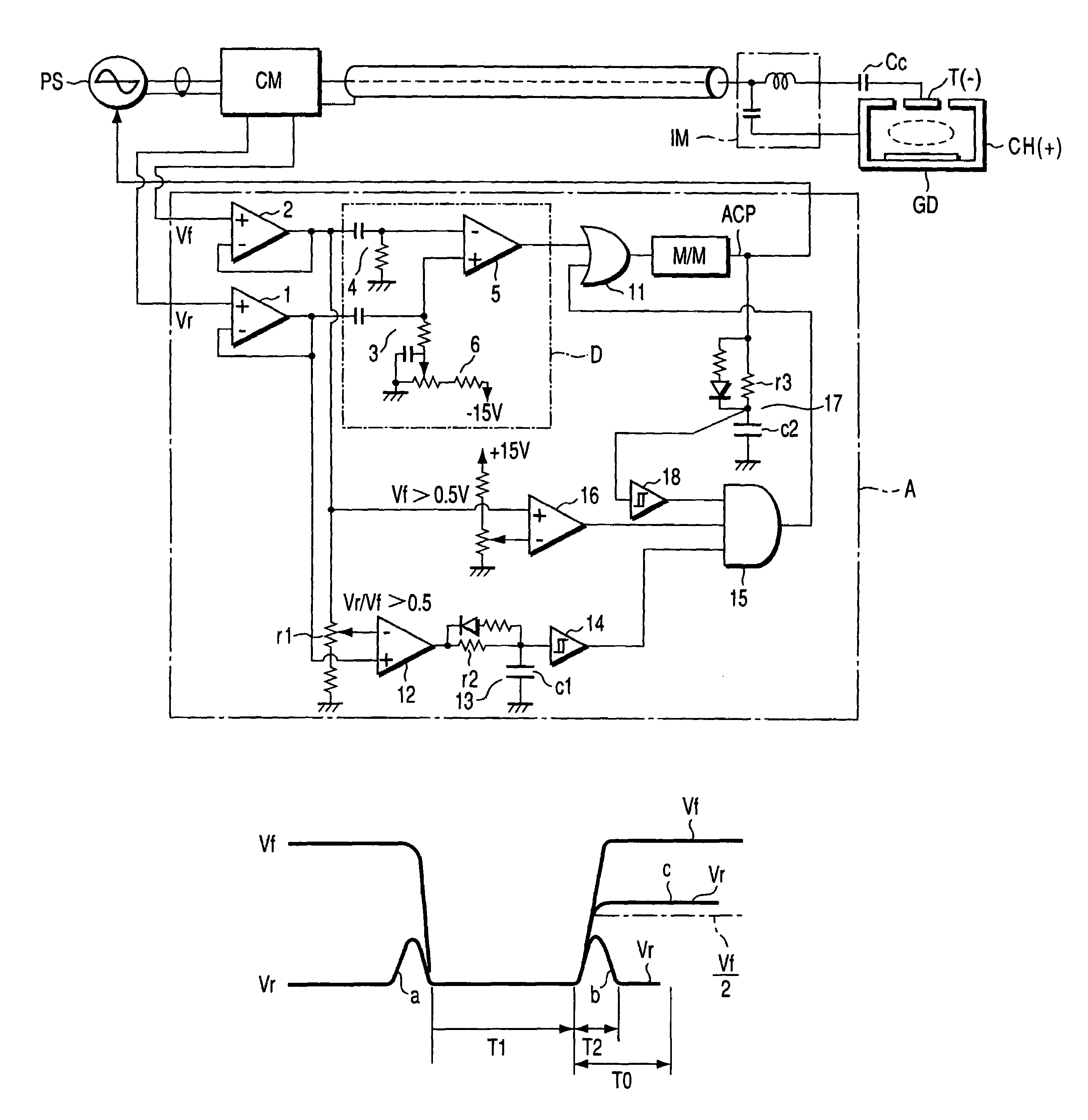
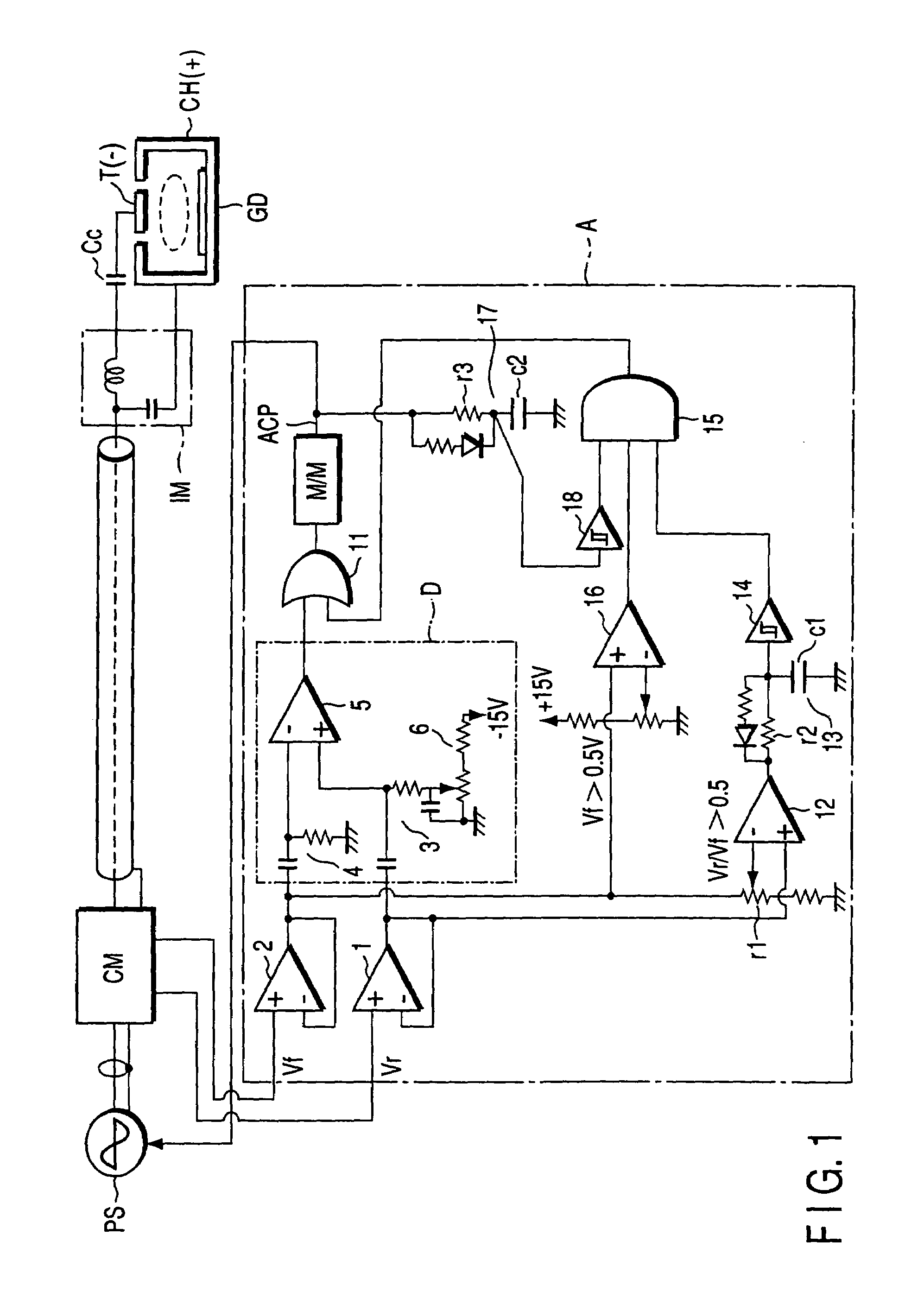
[0022]this invention will be described, with reference to FIG. 1. In FIG. 1, the components identical to those shown in FIG. 5 are designated at the same reference numerals.
[0023]In the first embodiment, the high-frequency power source PS is connected to a target T and a chamber CH by a coaxial cable, a power meter CM, a coaxial cable, an impedance-matching circuit IM and a DC-cutting capacitor Cc. Thus, power is supplied from the high-frequency power source PS, applying a voltage between the target T and the chamber CH. Note that “GD” in FIG. 5 is a glow-discharge device.
[0024]As long as glow discharge continues in the glow-discharge device GD, the high-frequency power source PS supplies power to the glow-discharge device GD so that the reflected-wave power and the traveling-wave power may be minimum and maximum, respectively. Thus, neither the reflected-wave power nor the traveling-wave power changes greatly. When arc discharge develops in the glow-discharge device GD, the reflect...
second embodiment
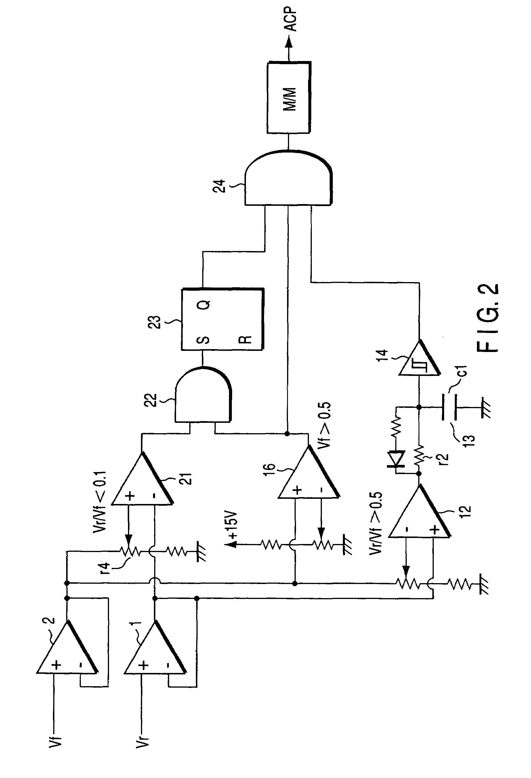
[0043]this invention will be described with reference to FIG. 2. The components identical to those shown in FIG. 1 are designated at the same reference numerals in FIG. 2 and will not be described in detail.
[0044]FIG. 2 is a circuit diagram of the arc-detecting circuit provided according to the second embodiment, which differs from the arc-detecting circuit A illustrated in FIG. 1. Note that the inputs to the comparators 12 and 16 are just the same as in the arc-detecting circuit A of FIG. 1.
[0045]The circuit shown in FIG. 2 has a comparator 21 that can detect that matching has been achieved.
[0046]The positive (+) input terminal of the comparator 21 receives one-tenth ( 1 / 10) of the traveling-wave voltage Vf output from the amplifier 2, through a voltage-dividing resistor r4. That is, the comparator 21 outputs a H-level signal when Vr / Vf becomes less than 0.1 (third level) (Vr / Vf<0.1, determining that the matching has been achieved.
[0047]The outputs of the comparators 16 and 21 are ...
third embodiment
[0053]the invention will be described with reference to FIG. 3. The components identical to those shown in FIG. 2 are designated at the same reference numerals in FIG. 3 and will not be described in detail. The circuit of FIG. 3 has a timer circuit 25 and a Schmidt circuit 26 that are connected in series between the AND circuits 22 and 24 which are identical to those shown in FIG. 2. The timer circuit 25 comprises a resistor r5 and a capacitor c3.
[0054]In the third embodiment, no arc-cutting pulse ACP can be output when the matching slowly shifts to make Vr / Vf greater than 0.5 (Vr / Vf>0.5). This is because the timer circuit 25 comprising the resistor r5 and capacitor c3 and the Schmidt circuit 26 is connected in series between the AND circuits 22 and 24.
[0055]The timer circuit 13, which is reset upon measuring time T1, may not be used in the third embodiment, while it cannot be dispensed with in the first and second embodiments.
[0056]Preset time To mentioned above may be 5 to 100 μs....
PUM
| Property | Measurement | Unit |
|---|---|---|
| Time | aaaaa | aaaaa |
Abstract
Description
Claims
Application Information