Methods and apparatus for managing clock skew

a technology of clock skew and apparatus, applied in the direction of generating/distributing signals, pulse techniques, instruments, etc., can solve the problems of clock skew, clock skew, clock skew,

Active Publication Date: 2007-11-27
GLOBALFOUNDRIES U S INC +1
View PDF3 Cites 28 Cited by
  • Summary
  • Abstract
  • Description
  • Claims
  • Application Information

AI Technical Summary

Problems solved by technology

Clock jitter relates to the inaccuracies inherent in generating the system clock signal.
The non-ideal characteristics of the system clock signals due to clock jitter affect all portions of the LSI circuit in the same way, irrespective of how the system clock signals are distributed to those portions of the circuit.
Clock skew relates to the inaccuracies introduced into the system clock signals by the distribution technique employed to split the system clock into many paths and deliver the clock signals to different portions of the digital circuit.
Statically occurring sources of clock skew are caused by the LSI design or manufacturing process irrespective of the operating conditions of the LSI circuit.
Unfortunately, the variations in the timing characteristics of the system clock signals due to clock skew result in undesirable errors in the operation of the digital circuitry of the LSI circuit.
For various reasons, these techniques have not been adequately successful in addressing the undesirable problems caused by clock skew.
The clock skew problem is exacerbated when separate clock trees and separate clock meshes are employed to deliver different clock frequencies to different portions of a circuit.
From that point onward, as the signals propagate along their respective clock trees toward their respective clock meshes, clock skew will generally become progressively worse as each length of wire and each device through which each signal travels introduces another opportunity for disparities in the speed of propagation of the respective signals to arise.
Conventional techniques for reducing the resulting clock skew between separate meshes are very complex.

Method used


Image

  • Methods and apparatus for managing clock skew
  • Methods and apparatus for managing clock skew
  • Methods and apparatus for managing clock skew

Examples


Embodiment Construction

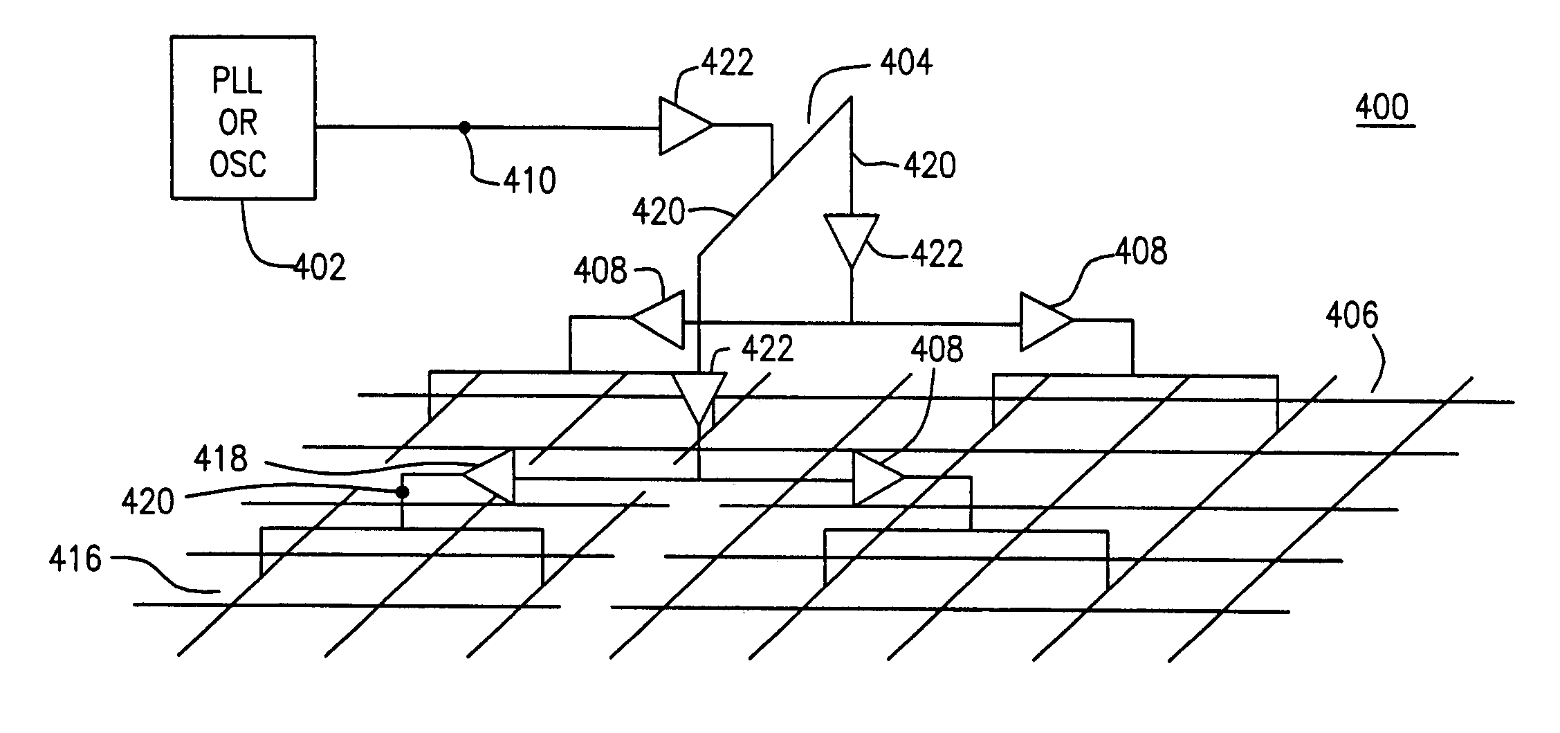
[0028]Herein, a signal generator may be implemented using a PLL, an oscillator or other device capable of generating a periodic signal. Herein, a final buffer may be a clock buffer located at or near a junction between a clock tree and a clock mesh. However, the term “final buffer” is not limited to the foregoing description. Referring now to the drawings, wherein like numerals indicate like elements, there is shown in FIG. 4 a semiconductor device 400, such as an LSI circuit.

[0029]FIG. 4 is a schematic diagram of a circuit 400 in accordance with one or more embodiments of the present invention. Circuit 400 includes PLL, oscillator or other clock source 402, clock tree 404, a first clock mesh 406, and a second clock mesh 416. Oscillator 402 is a conventional device for providing a periodic signal, and is known in the art. Clock tree 404 includes a network of conductive segments 420, clock buffers 422, and final buffers 408 and 418 to fan the clock signal 410 to multiple points on cl...


PUM


Abstract

An apparatus is disclosed which includes a signal generator providing a first signal having a first frequency; a clock tree operative to propagate the first signal to at least one clock mesh of the apparatus; and a final buffer operative to receive the first signal, provide a second signal having a second frequency, synchronize the second signal with the first signal, and propagate the synchronized second signal to at least one other clock mesh of the apparatus.

Description

BACKGROUND OF THE INVENTION[0001]The present invention relates to managing clock skew when separate clock meshes are employed to provide different clock frequencies to different portions of a large scale integrated (LSI) circuit.[0002]A system clock signal is often used by digital circuitry, such as digital circuitry implemented using a LSI circuit, to synchronously execute certain logic functions. For example, ultra-deep sub-micron (UDSM) microprocessors employ digital circuitry that use system clock signals to synchronously execute logic functions. These microprocessors operate at system clock frequencies of 1 GHz and higher. The system clock signal of a given LSI circuit is often split into many paths to service many different portions of the digital circuitry. Ideally, the system clock signals at different portions of the digital circuitry exhibit exactly the same timing characteristics so that the different portions of the digital circuitry operate in exact synchronization. In ...

Claims


Application Information

Patent Timeline
Patent Type & Authority Patents(United States)
IPC IPC(8): G06F1/04
CPCG06F1/10
Inventor TAKANO, CHIAKIWEITZEL, STEPHEN D.
Owner GLOBALFOUNDRIES U S INC
Why Eureka
Try Eureka