
Image forming apparatus with printing data correction arrangement

Inactive Publication Date: 2007-11-27
OKI DATA CORP
View PDF12 Cites 4 Cited by
  • Summary
  • Abstract
  • Description
  • Claims
  • Application Information

AI Technical Summary

Benefits of technology

[0019]The present invention has been made in view of the above-described issue with an object of providing an image forming apparatus capable of suppressing the variation of dot diameters due to the effect of immediately adjoining or neighboring light emitting elements.

Problems solved by technology

However, there is a problem that the dot diameter variation cannot be resolved to a sufficient degree, since, when neighboring light emitting elements emit the light at the same time, some dots may have diameters that differ from the set value.
As a result, an electrostatic latent image formed on the photosensitive drum is distorted and accordingly a toner image distorted, causing degradation in printing quality.

Method used


Image

  • Image forming apparatus with printing data correction arrangement
  • Image forming apparatus with printing data correction arrangement
  • Image forming apparatus with printing data correction arrangement

Examples


first embodiment

A First Embodiment

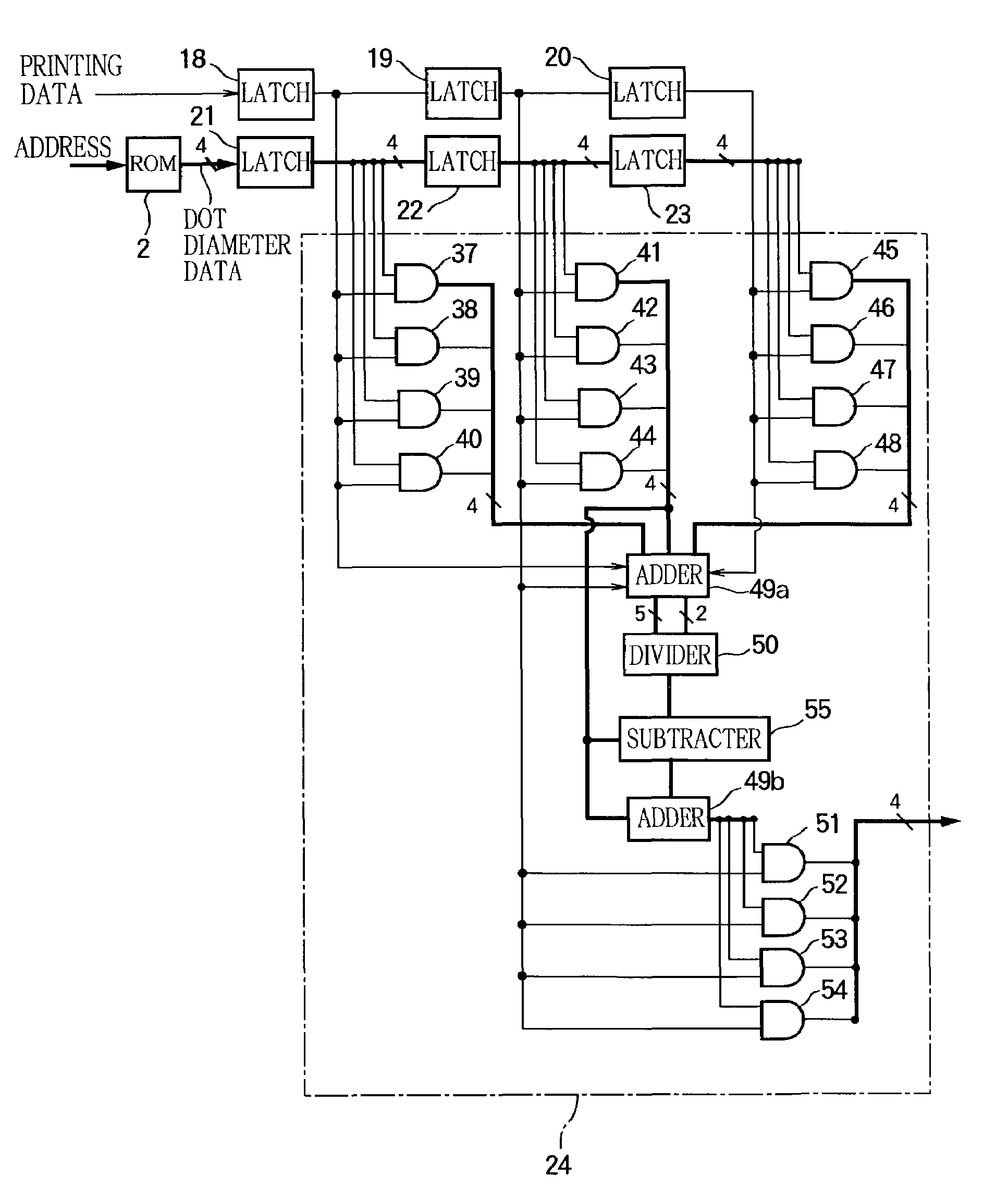
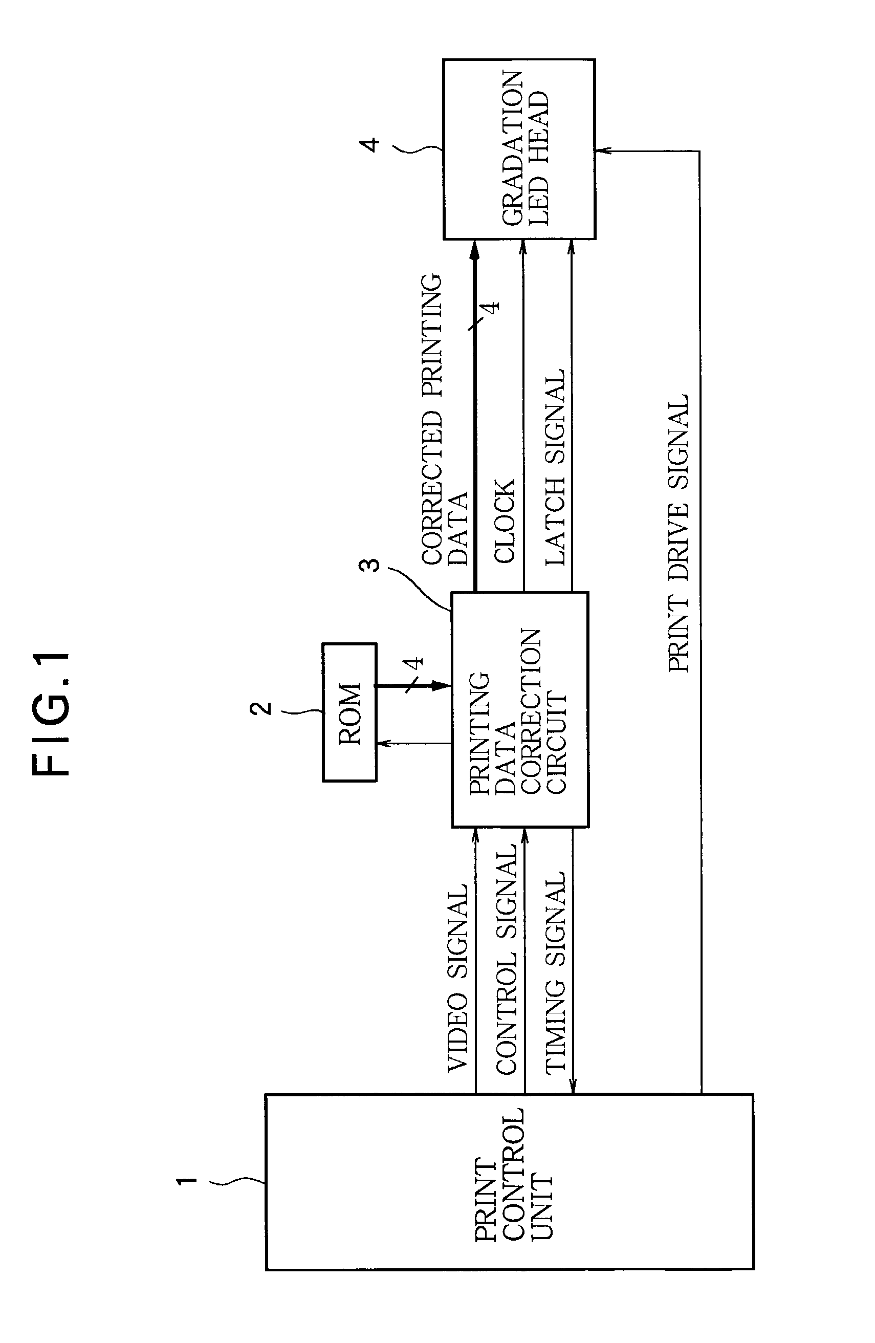
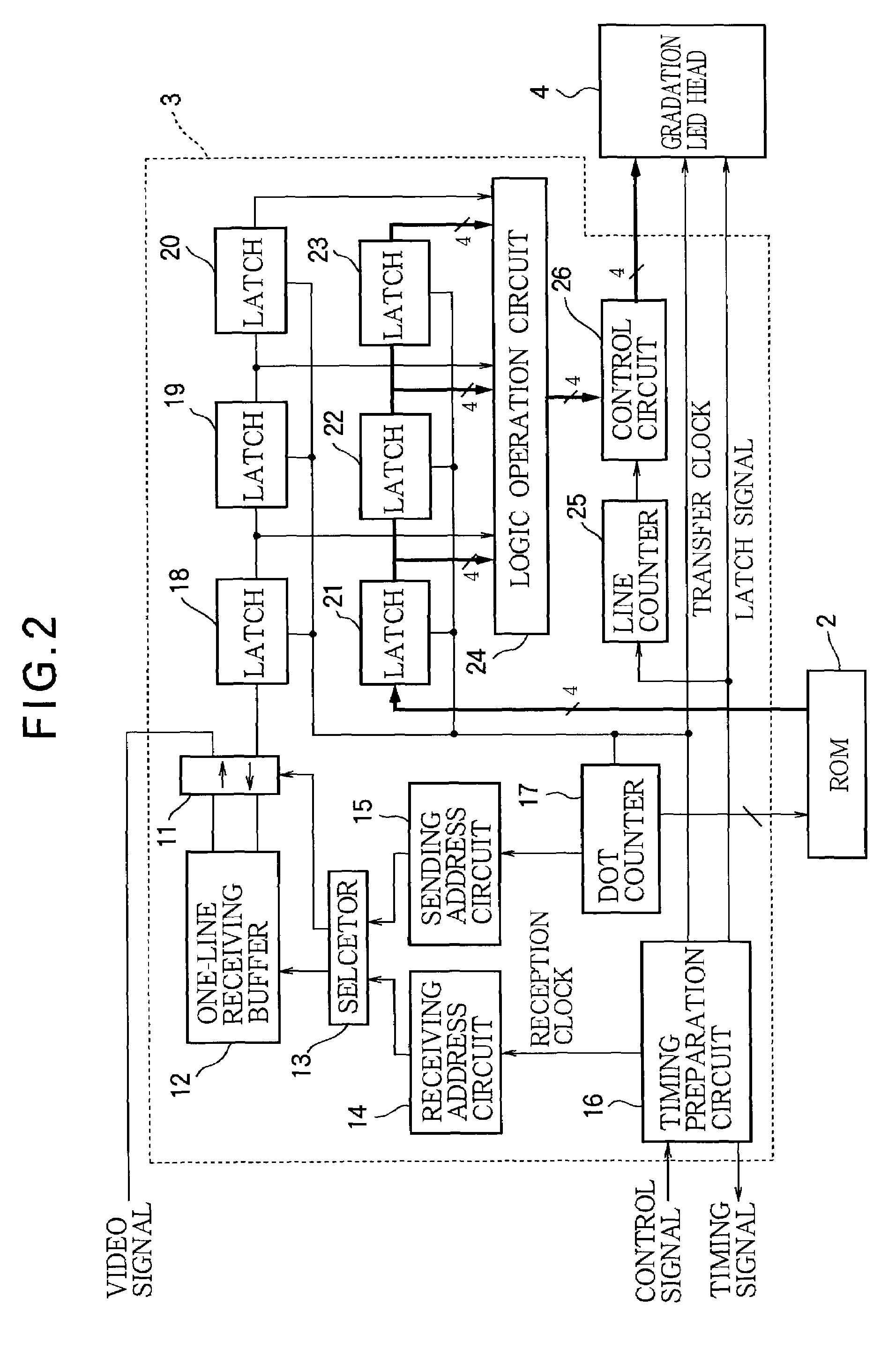
[0071]FIG. 1 shows a structure of a first embodiment of the image forming apparatus according to the invention. As shown in this figure, the apparatus includes a print control unit 1, a printing data correction circuit 3, a gradation LED head 4, and a non-volatile memory or a ROM 2 (for example, EEPROM). The print control unit 1 supplies the printing data correction circuit 3 with a video signal including printing data and a control signal for controlling the operation of the printing data correction circuit 3. The printing data correction circuit 3 outputs a timing signal for synchronization with the print control unit 1 to the print control unit 1. The printing data correction circuit 3 supplies the gradation LED head 4 with corrected printing data output in synchronization with the timing signal, a latch signal for latching the corrected printing data in the LED head 4, and a clock. The ROM 2 connected to the printing data correction circuit 3 is to store dot di...

second embodiment

A Second Embodiment

[0105]FIG. 15 shows a structure of a second embodiment of the image forming apparatus according to the invention. The second embodiment has a structure similar to that of the first embodiment shown in FIG. 1, however, it differs from the first embodiment in that the video signal output from the print control unit to the printing data correction circuit and the printing data are multivalued data and not binary data.

[0106]As shown in FIG. 15, the image forming apparatus of the second embodiment includes a print control unit 1, a printing data correction circuit 3A, a gradation LED head 4, and a non-volatile memory or ROM 2 (EEPROM, for example). The print control unit 1 supplies the printing data correction circuit 3A with a video signal including printing data and a control signal for controlling the operation of the printing data correction circuit 3A. The printing data correction circuit 3A outputs a timing signal for synchronization with the print control unit 1...

third embodiment

A Third Embodiment

[0128]The above described embodiments can suppress the effect of the lens-to-lens variation in the MTF value for each of relatively small areas constituting a print pattern. However, the effect is not removed sufficiently when the print pattern, which occupies a relatively large area, is viewed as a whole. Accordingly, a third embodiment of the invention is configured to correct diameters of dots constituting a pattern of a certain area in a lot to remove the effect of the lens-to-lens variation in the MTF value.

[0129]FIG. 20 shows a structure of the third embodiment of the image forming apparatus according to the invention. As shown in FIG. 20, this apparatus includes a print control unit 1, a printing data correction circuit 3B, a gradation LED head 4, and a non-volatile memory device or ROM 2 (EEPROM, for example). The print control unit 1 supplies the printing data correction circuit 3B with a video signal including printing data and a control signal for contro...


PUM


Abstract

An image forming apparatus with a plurality of driven elements has a memory for storing driving data on each of the driven elements for driving the driven elements, and a computing unit that reads, from the memory, driving data on a driven element corresponding to a dot of interest and driving data on at least one driven element corresponding to at least one dot included in an area of predetermined dimensions in which the dot of interest is included, and produces corrected printing data based on the driving data read from the memory and on printing data on the dot of interest input from a higher control unit. The image forming apparatus performs printing by driving the driven element corresponding to the dot of interest by use of the corrected printing data.

Description

FIELD OF THE INVENTION[0001]This invention relates to an image forming apparatus such as a printer, a copier, and a facsimile machine.BACKGROUND OF THE INVENTION[0002]A printer of the electrophotographic type, for example, is configured to apply light to a charged photosensitive drum in a selective manner depending on printing data to form an electrostatic latent image. Toner is deposited on the electrostatic latent image to form a toner image and the toner image is transferred to a sheet of paper, where it is fused into place.[0003]FIG. 30 is a block diagram of a printer control circuit for use in such a conventional electrophotographic printer. FIGS. 31 and 32 are timing diagrams explaining the printing operation of the conventional electrophotographic printer. In FIG. 30, a reference numeral 1 denotes a print control unit comprised of a microprocessor, a ROM, a RAM, an input / output port, a timer and so on. The print control unit 1, which is included in a printing unit of the prin...

Claims


Application Information

Patent Timeline
IPC IPC(8): B41J2/435G06K15/12H04N1/40
CPCG06K15/1247H04N1/40031G06K2215/0085
Inventor SATO, TOSHIKI
Owner OKI DATA CORP
Features
  • Generate Ideas
  • Intellectual Property
  • Life Sciences
  • Materials
  • Tech Scout
  • Unparalleled Data Quality
  • Higher Quality Content
  • 60% Fewer Hallucinations
Learn More