

Image-formation optical system, and imaging system incorporating the same
an image-formation optical system and imaging system technology, applied in the field of image-formation optical systems and imaging systems, can solve the problems of high performance that cannot be expected, the brightness of an image changes extremely between the central and the peripheral portion of the image, and all the prior arts have problems in conjunction with performance and size, and achieves significant compactness and high performance.
- Summary
- Abstract
- Description
- Claims
- Application Information
AI Technical Summary
Benefits of technology
Problems solved by technology
Method used
Image

Examples
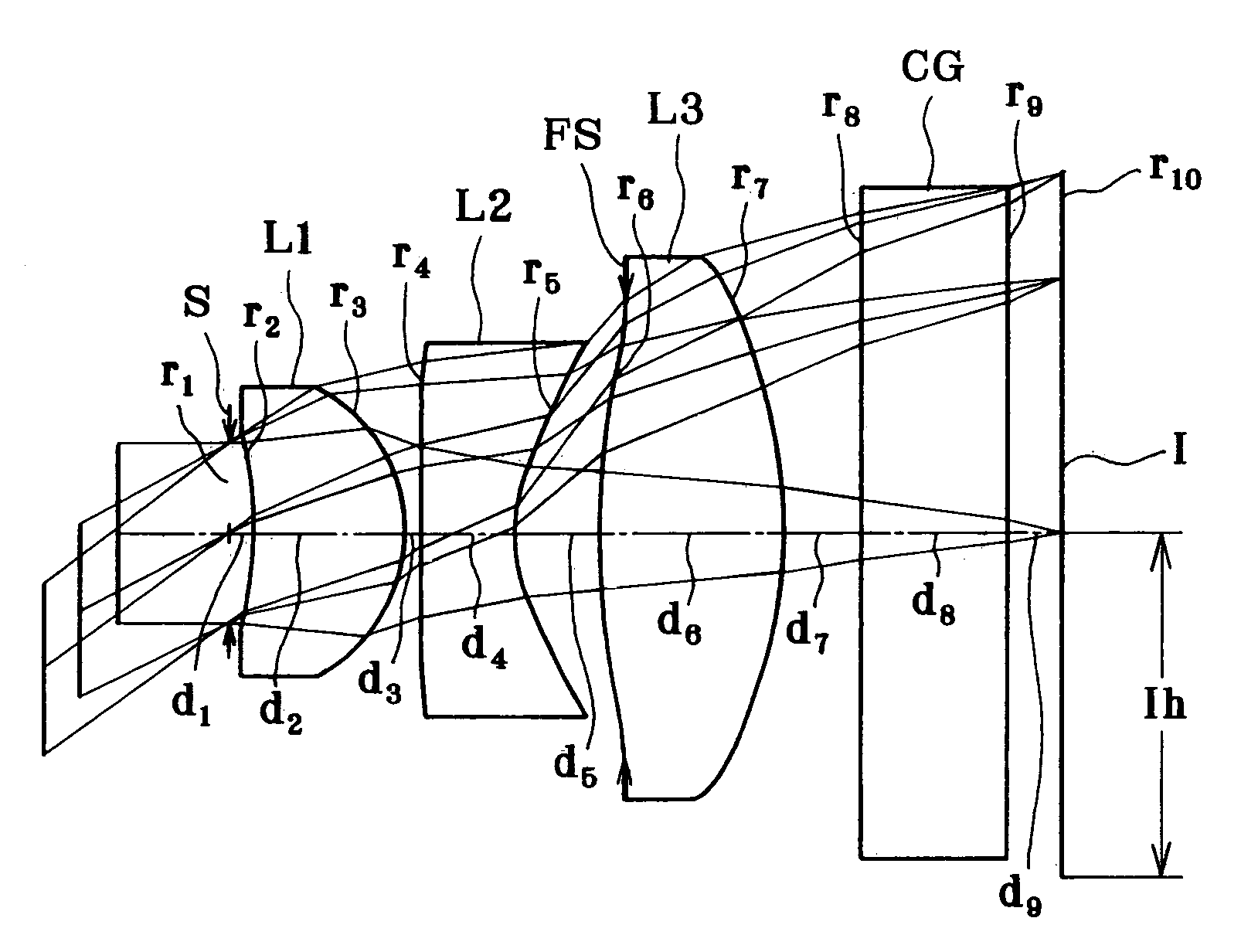
example 4
[0738]
r1 = ∞(stop)d1 = 0.1500r2 = −3.7560(Aspheric)d2 = 1.1970nd1 = 1.52542νd1 = 55.78r3 = −0.7727(Aspheric)d3 = 0.1000r4 = 6.2100(Aspheric)d4 = 0.6000nd2 = 1.58423νd2 = 30.49r5 = 0.9511(Aspheric)d5 = 0.5038r6 = 4.5116(Aspheric)d6 = 0.7107nd3 = 1.52542νd3 = 55.78r7 = 29.5761(Aspheric)d7 = 0.7000r8 = ∞d8 = 1.0000nd4 = 1.51633νd4 = 64.14r9 = ∞d9 = 0.3371r10 = ∞(Image Plane)Aspherical Coefficients2nd surfaceK = 1.8547A4 = −1.9182 × 10⁻¹A6 = 1.5418 × 10⁻¹A8 = −6.5395 × 10⁻¹A10 = 5.0643 × 10⁻¹³rd surfaceK = −2.9572A4 = −1.5178 × 10⁻¹A6 = −1.5283 × 10⁻²A8 = 5.6949 × 10⁻²A10 = −5.1828 × 10⁻²⁴th surfaceK = 0A4 = 5.6577 × 10⁻²A6 = 3.2526 × 10⁻²A8 = −1.9586 × 10⁻²A10 = 2.2295 × 10⁻³⁵th surfaceK = −6.2752A4 = 4.2023 × 10⁻²A6 = 4.1358 × 10⁻²A8 = 4.5499 × 10⁻³A10 = −9.1887 × 10−36th surfaceK = 0A4 = −3.9926 × 10⁻²A6 = 3.5414 × 10⁻²A8 = −1.9119 × 10⁻²A10 = 2.5213 × 10−37th surfaceK = 0A4 = 4.4096 × 10⁻²A6 = −1.3953 × 10⁻²A8 = −1.1535 × 10⁻³A10 = −1.3319 × 10⁻⁴
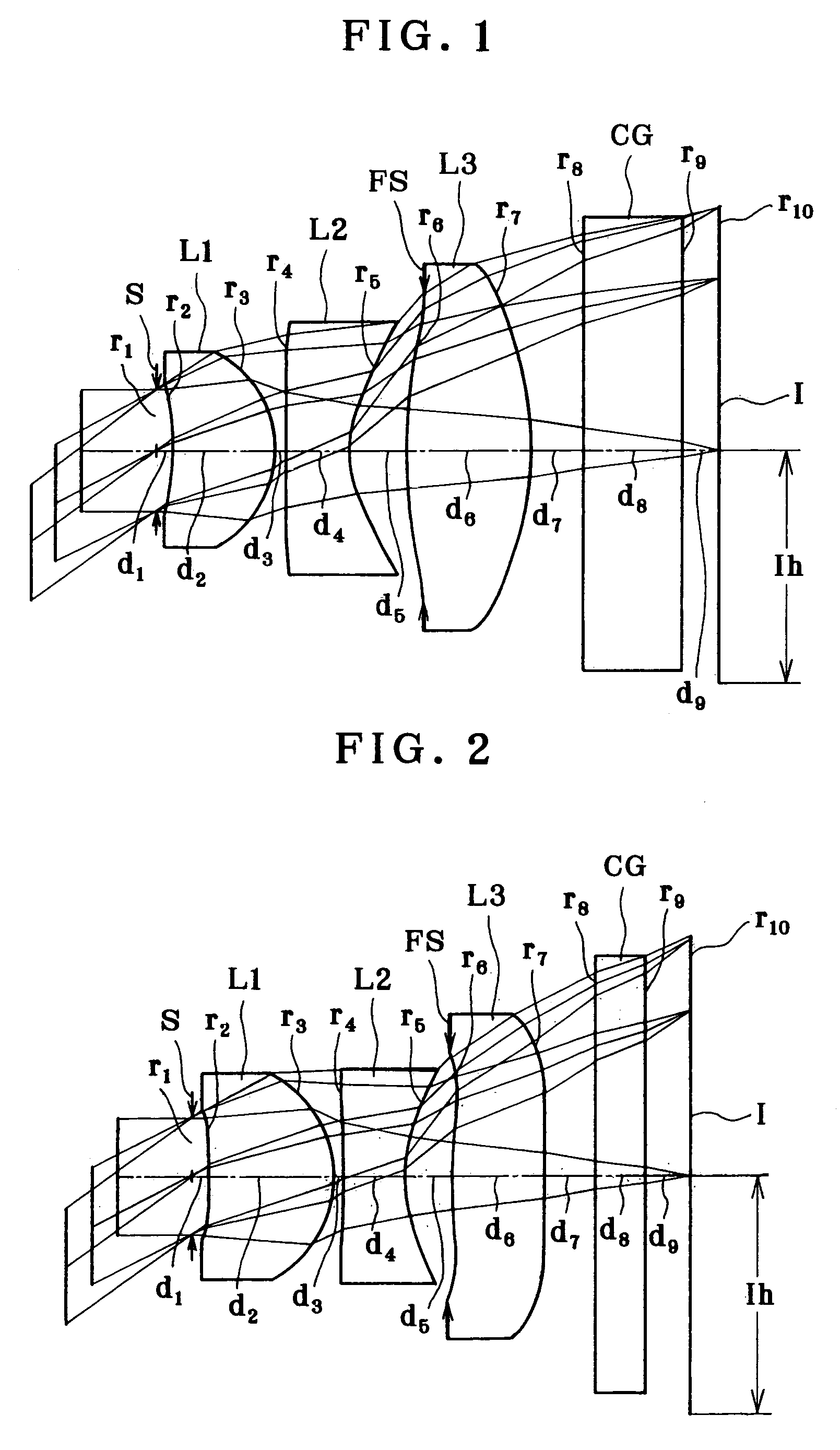
example 5
[0739]
r1 = ∞(Stop)d1 = 0.1500r2 = −4.2723(Aspheric)d2 = 0.9859nd1 = 1.52542νd1 = 55.78r3 = −0.7970(Aspheric)d3 = 0.2057r4 = −20.1610(Aspheric)d4 = 0.6000nd2 = 1.58423νd2 = 30.49r5 = 0.9497(Aspheric)d5 = 0.4803r6 = 4.6739(Aspheric)d6 = 1.2757nd3 = 1.52542νd3 = 55.78r7 = −2.3387(Aspheric)d7 = 1.0000r8 = ∞d8 = 1.0000nd4 = 1.51633νd4 = 64.10r9 = ∞d9 = 0.1430r10 = ∞(Image Plane)Aspherical Coefficients2nd surfaceK = 22.5176A4 = −1.8700 × 10⁻¹A6 = 2.8089 × 10⁻¹A8 = −1.1438A10 = 9.2846 × 10⁻¹³rd surfaceK = −2.5781A4 = −1.5623 × 10⁻¹A6 = −7.6367 × 10⁻²A8 = 9.3334 × 10⁻²A10 = −8.7816 × 10⁻²⁴th surfaceK = 0A4 = −5.1907 × 10⁻³A6 = 8.8894 × 10⁻⁴A8 = 1.7568 × 10⁻²A10 = −3.6261 × 10⁻³⁵th surfaceK = −5.2062A4 = 4.3573 × 10⁻³A6 = 1.1495 × 10⁻²A8 = −1.2427 × 10⁻²A10 = 4.9772 × 10−36th surfaceK = 0A4 = −4.4377 × 10⁻²A6 = 4.4915 × 10⁻²A8 = −1.6658 × 10⁻²A10 = 8.7133 × 10−47th surfaceK = −5.5015A4 = −2.6667 × 10⁻²A6 = 5.1523 × 10⁻³A8 = 5.8435 × 10⁻³A10 = −2.1188 × 10⁻³
[0740]FIGS. 59-63 are aberration di...
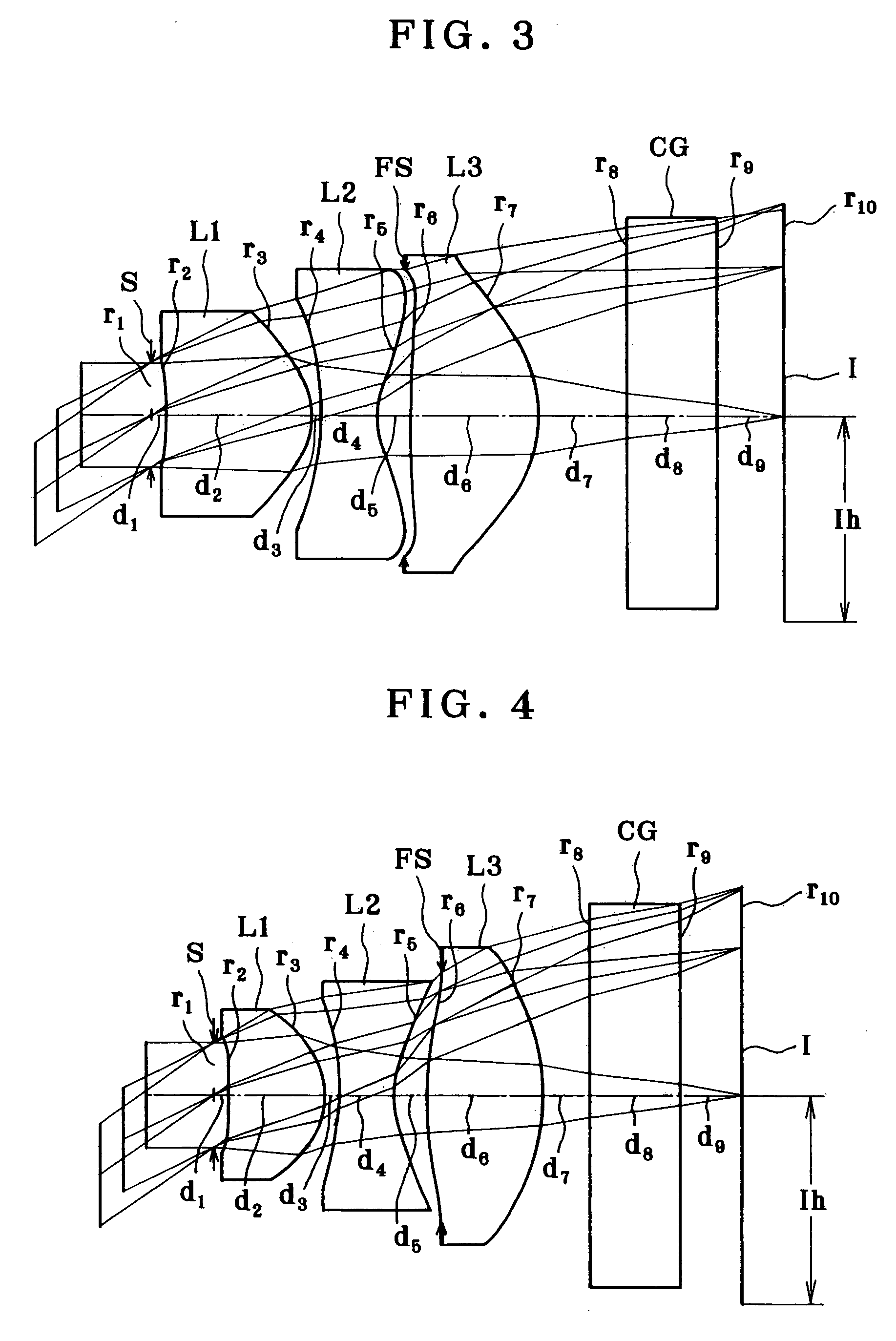
example 1
[0815]
r1 = ∞(Stop)d1 = 0.1200r2 = −2.6726(Aspheric)d2 = 0.9687nd1 = 1.49241νd1 = 57.66r3 = −0.9138(Aspheric)d3 = 0.1000r4 = 2.8532(Aspheric)d4 = 0.8000nd2 = 1.58423νd2 = 30.49r5 = 0.9461(Aspheric)d5 = 0.6800r6 = 3.3561(Aspheric)d6 = 1.2969nd3 = 1.49241νd3 = 57.66r7 = −5.5439(Aspheric)d7 = 0.5000r8 = ∞d8 = 1.0000nd4 = 1.51633νd4 = 64.14r9 = ∞d9 = 0.1749r10 = ∞(Image Plane)Aspherical Coefficients2nd surfaceK = 0A4 = −1.2923 × 10⁻¹A6 = −2.6271 × 10⁻²A8 = −7.6282 × 10⁻²A10 = 0.00003rd surfaceK = −2.6868A4 = −1.5367 × 10⁻¹A6 = 5.0013 × 10⁻²A8 = −4.5494 × 10⁻²A10 = 0.00004th surfaceK = −18.3300A4 = 8.0480 × 10⁻²A6 = −8.9950 × 10⁻³A8 = 7.8434 × 10⁻⁴A10 = 0.00005th surfaceK = −4.2745A4 = 2.7143 × 10⁻²A6 = 1.4933 × 10⁻²A8 = 1.3242 × 10⁻⁴A10 = 0.00006th surfaceK = −34.8663A4 = 3.2814 × 10⁻²A6 = −4.4307 × 10⁻²A8 = 2.3091 × 10⁻²A10 = −5.9202 × 10−37th surfaceK = 7.2292A4 = 1.3056 × 10⁻²A6 = 2.3976 × 10⁻³A8 = −1.2672 × 10⁻³A10 = −8.5404 × 10⁻⁵
PUM
 Abstract
Description
Claims
Application Information