Aerodynamic trip for a combustion system

a combustion system and aerodynamic technology, applied in the direction of machines/engines, efficient propulsion technologies, lighting and heating apparatus, etc., can solve the problems of poor dynamic temperature distribution and unsatisfactory combustion noise, and achieve the effect of reducing combustion noise, improving combustion temperature distribution, and reducing combustion nois

Active Publication Date: 2007-12-04
PRATT & WHITNEY CANADA CORP
View PDF23 Cites 13 Cited by
  • Summary
  • Abstract
  • Description
  • Claims
  • Application Information

AI Technical Summary

Benefits of technology

[0005]In another aspect, the invention provides at least a gas turbine engine comprising: a combustor portion including at least one combustor, the combustor having a plurality, of holes therein for admitting combustion air into the combustor; a casing defining at least one chamber therein, the chamber containing the combustor and a volume of air around at least a portion of the combustor; a compressor portion communicating with the chamber via a compressor outlet for delivering compressed air to the chamber for subsequent admission into the combustor; and a ring extending into the chamber substantially continuously around the chamber so as to extend partially into an air flow exiting the compressor outlet into the chamber, the ring sized and positioned in the chamber to, in use, cause a step change in direction and pressure of at least a portion of the air flow, the step change adapted to effect a redistribution of air around the combustor to thereby achieve at least one of reduced combustion noise and more uniform temperature distribution in the combustor.
[0007]In another aspect, the invention provides at least a gas turbine engine comprising: a gas generator portion including at least a compressor, a combustor and a chamber around the combustor, the gas generator in use having an air flow from the compressor entering the chamber and guided thereby to the combustor; the air flow providing a source of combustion air to the combustor; and at least one trip disposed in the chamber at a location fluidly intermediate the compressor and the combustor, the trip adapted to extend into the air flow and extend substantially transversely relative to an initial direction of the air flow in the chamber, the trip adapted in use to create a predetermined step change increase in pressure drop of the air flow to thereby effect a predetermined air flow redistribution in the chamber, said air flow redistribution predetermined to improve at least one of an air pressure distribution outside the combustor and a fluctuation phase shift in the air flow adapted to reduce combustion noise.
[0009]In another aspect, the invention provides at least a method of providing a gas turbine engine, the method comprising the steps of: determining a configuration for a compressed air system, a combustor and a casing chamber surrounding the combustor, the configuration including an air flow path from compressed air system through the casing chamber and into the combustor; determining an initial operating air pressure distribution occurring in the compressed air in the chamber around the combustor; determining a desired air pressure redistribution in the compressed air in the chamber around the combustor, the redistribution adapted to provide at least one of reduced combustion noise and improved temperature distribution in the combustor; and introducing an intervention in the casing chamber, the intervention extending into the flow path and adapted to effect the determined air pressure redistribution.
[0010]In another aspect, the invention provides at least a method of improving combustion, the method comprising the steps of: providing a compressed air flow, the compressed air flow having an acoustic and hydrodynamic structure imposed during a compression process; restructuring the acoustic and hydrodynamic structure to provide a preselected second acoustic and hydrodynamic structure, the second structure preselected to cause a acoustic and hydrodynamic phase shift in at least a portion of the compressed air flow, the phase shift being selected adapted to reduce combustion noise; providing the restructured compressed air flow to a combustor for use in combustion.
[0011]In another aspect, the invention provides at least a method of improving combustion in a gas turbine engine, the method comprising, the steps of: selecting a gas turbine engine, the engine having at least a compressor providing a source of compressed air, a combustor and a chamber surrounding the combustor, the compressor, chamber and combustor in serial fluid communication for transmitting the air from the compressor to the combustor for combustion; and modifying the gas turbine engine by inserting at least one aerodynamic trip into the chambers the trip adapted to effect at least one of a pressure redistribution around the combustor and a phase shift in pressure fluctuations in at least a portion of the air in the chamber, the phase shift adapted to reduce combustion noise.

Problems solved by technology

In the combustion of fuels in a combustion chamber like that of an industrial gas turbine or an aircraft gas turbine engine, the combustion process can cause instabilities or pressure fluctuations which, under unfavourable conditions, present undesirable combustion noise and a poor dynamic temperature distribution.

Method used


Image

  • Aerodynamic trip for a combustion system
  • Aerodynamic trip for a combustion system
  • Aerodynamic trip for a combustion system

Examples


Embodiment Construction

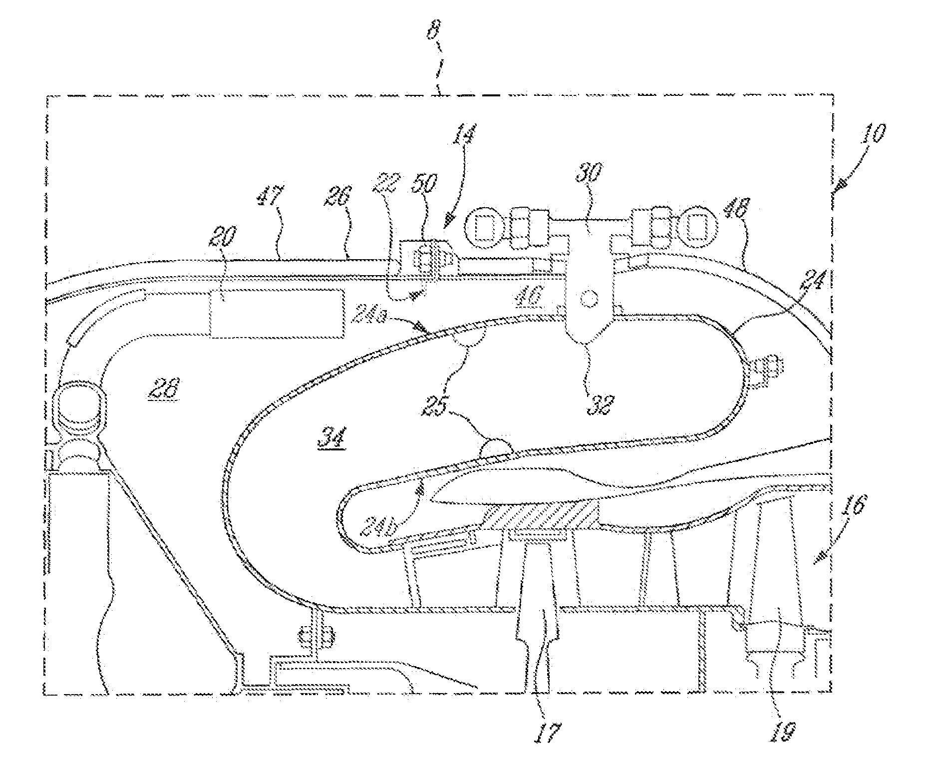
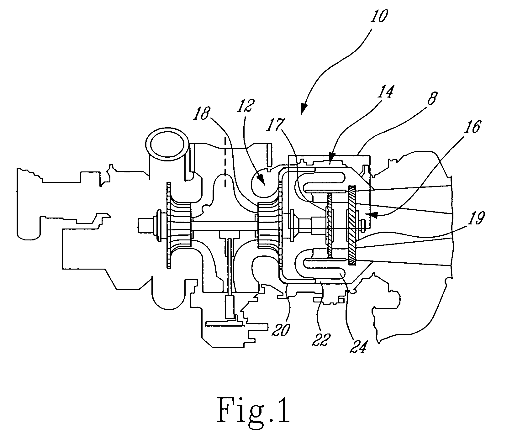
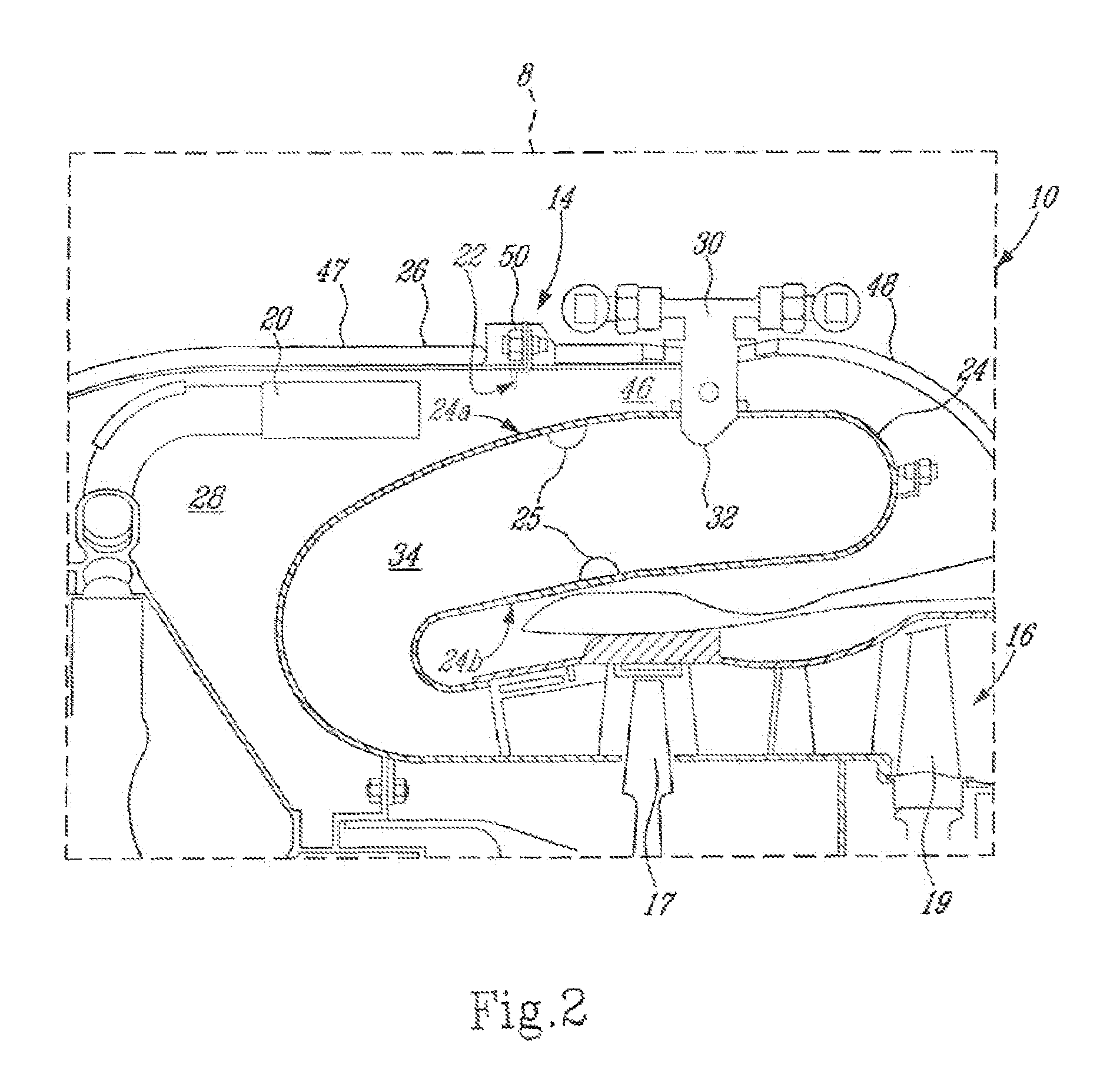
[0021]Referring to FIG. 1, a gas turbine engine 10, which is illustrated as an APU but can be any type of gas turbine engine, includes an embodiment of the present invention. Engine 10 generally comprises a compressor region 12, a combustor region 14 and a turbine region 16. The compressor region 12 generally includes a high pressure compressor 18 for providing a high pressure compressor air flow for combustion and for cooling of the engine. A compressor diffuser 20 is positioned downstream of the high pressure compressor 18 and extends into the combustor region 14 for reducing the velocity which increases the pressure of compressor air flow and for delivering the compressor air flow to the combustor region 14. According to the present invention, a tripping device, in this embodiment preferably an aerodynamic trip ring 22, is provided in the combustor region 14 for intervening in the compressor air flow before the compressor air flow enters a combustor 24 for combustion, as will be ...


PUM


Abstract

A apparatus and method for improving combustion by improving at least one of temperature distribution in the combustor, pressure distribution around the combustor and combustion noise level in the combustor, by redistributing air around the combustor to modify the structure of the air flow prior to entry into the combustor.

Description

TECHNICAL FIELD[0001]The present invention relates to a method and apparatus for improving combustion, and particularly gas turbine engine combustion.BACKGROUND OF THE INVENTION[0002]In the combustion of fuels in a combustion chamber like that of an industrial gas turbine or an aircraft gas turbine engine, the combustion process can cause instabilities or pressure fluctuations which, under unfavourable conditions, present undesirable combustion noise and a poor dynamic temperature distribution.[0003]In particular, there is a need to improve temperature distribution and noise level of gas turbine engine combustion, and particularly so in APU for aircraft.SUMMARY OF THE INVENTION[0004]One object of the present invention is to provide improved combustion, and particularly that which would be beneficial to gas turbine engines.[0005]In another aspect, the invention provides at least a gas turbine engine comprising: a combustor portion including at least one combustor, the combustor havin...

Claims


Application Information

Patent Timeline
Patent Type & Authority Patents(United States)
IPC IPC(8): F02C1/00F23R3/00F23R3/04
CPCF23R3/002F23R3/04F23D2210/00Y02T50/675F23R2900/00014Y02T50/60
Inventor ALKABIE, HISHAM
Owner PRATT & WHITNEY CANADA CORP
Why Eureka
Try Eureka