Flexible pipe connected to an end fitting

a flexible pipe and end fitting technology, applied in the direction of flexible pipes, hose connections, pipes, etc., can solve the problems of limiting the problem of the structure flexibility transition, and reducing the load bearing capacity of the element, so as to avoid substantial bending of individual armouring wires and simplify the mounting of the flexible pipe

Inactive Publication Date: 2007-12-04
NKT FLEXIBLES IS
View PDF25 Cites 13 Cited by
  • Summary
  • Abstract
  • Description
  • Claims
  • Application Information

AI Technical Summary

Benefits of technology

[0024]An advantage of the invention is that in a loaded situation comprising a combination of internal pressure and external tension and where the armouring wires will elongate elastically leading to a change in the helical angle of the armouring wires, a pipe structure according to the invention will experience a slight twist and a controlled bending of the armouring wires on the surface of the support unit (due to a possible change in the base point of contact of the armouring wire with the support unit induced by the change of helical angle), thereby avoiding substantial bending of the individual armouring wires. This is for example of particular importance when the armouring wires are formed of a composite material. A complete and simple anchoring can then be incorporated in the end fitting design at any point after the ‘straight-line-end-point’ on the support unit (in the direction of the end fitting, i.e. when viewed from the pipe towards the end fitting), as the wire after this point is only stressed in its own direction.
[0025]The various parts of an end fitting may preferably be made of structural materials e.g. metals such as steel, titanium, aluminium, reinforced polymers such as fibre glass / polyester, carbon-fibre / epoxy, etc. The parts may e.g. be manufactured by a numerically controlled machine or by moulding.
[0026]In an embodiment of the invention, the wire-end-fitting-section is arranged to follow a predefined termination path between said wire-pipe-exit-point and one of said anchoring elements when said pipe structure is in an unloaded condition. The dynamic range of locations of the wire-pipe-exit-point and the straight-line-end-point may be predetermined according to the normal operating conditions of the pipe structure. The part of the wire-end-fitting-section of the armouring wire that is located after the dynamic range of locations of the straight-line-end-point (when viewed in a direction of the end fitting) may be fixed to a predetermined path on the support unit (e.g. using guiding channels or the like) to simplify the mounting of the flexible pipe to the end fitting.
[0027]In an embodiment of the invention, the straight-line-section is essentially unsupported between said wire-pipe-exit-point and said straight-line-end-point on said support unit. The term ‘essentially unsupported’ is in the present context taken to mean having a negligible effect on the deformation behaviour of the wire.
[0028]In an embodiment of the invention, the straight-line-section extends away from said longitudinal axis when viewed from said wire-pipe-exit-point.
[0029]In an embodiment of the invention, the straight-line-section of said armouring wire has a tangential point of contact with said support unit in said straight-line-end-point. In this embodiment, the armouring wire has a free (i.e. mechanically unrestricted) linear path between the points of contact with the underlying pipe layer and the support unit. Alternatively, the armouring wire may be strained in contact with (but without locking it to) the support unit e.g. by a surrounding body (e.g. in the form of an assisting element, see later), in which case the slope of the straight-line-section of the armouring wire may deviate from the tangent to the support unit at the point of contact.

Problems solved by technology

A conventional metallic armoured pipe is very stiff both radially and axially, thus limiting the problem of the transition in flexibility of the structure from the running length of pipe to the connector unit.
Further, a conventional steel armouring element, wire, may yield to a local intensity of stress, caused by an abrupt change in stiffness, without reducing the load bearing capacity of the element.
For a composite reinforced un-bonded flexible pipe, no solutions are available to facilitate the transition in stiffness of the pipe and connector structure without drastically reducing the load bearing capacity of the composite armour.

Method used


Image

  • Flexible pipe connected to an end fitting
  • Flexible pipe connected to an end fitting
  • Flexible pipe connected to an end fitting

Examples


Embodiment Construction

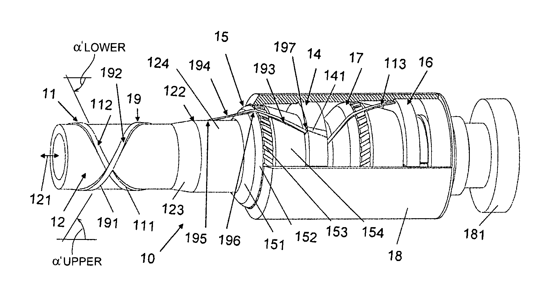
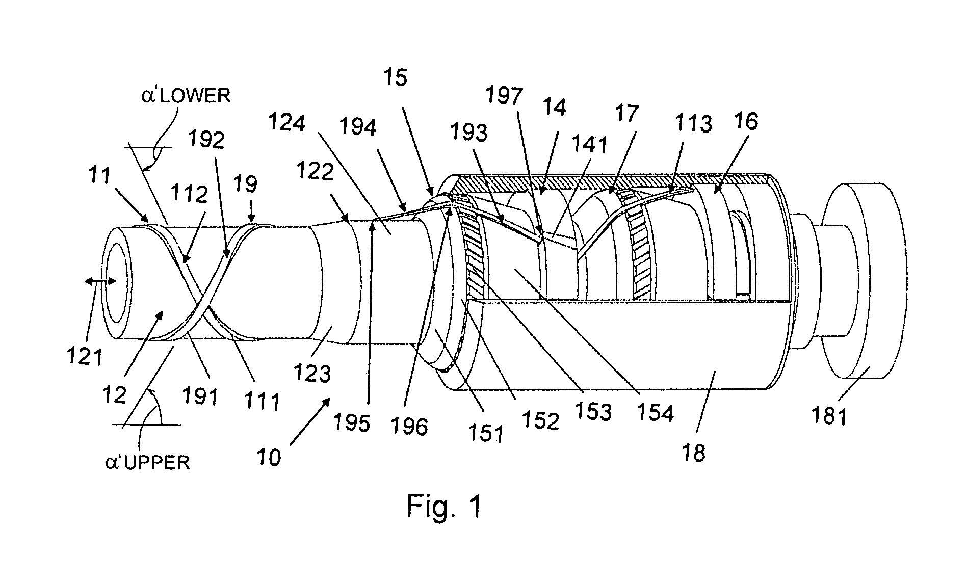
[0097]FIG. 1 shows a pipe structure according to the invention wherein an open end of a flexible pipe is connected to an end fitting, the flexible pipe comprising armouring wires that are locked to the end fitting in anchoring elements thereby fixing the flexible pipe to the end fitting.

[0098]The pipe structure 10 (comprising a flexible pipe and an end fitting) comprises two armouring layers, a lower armouring layer 11 and an upper armouring layer 19, each comprising a helically wound armouring wire (111 and 191, respectively). For clarity, only one armouring wire of each layer is shown in the drawing. It should be noted that the armouring wires 111 and 191 may represent examples of a multitude of armouring wires constituting the lower and upper armouring layer, respectively. It should further be noted that the parts 193, 113 (see later) of the armouring wires of the upper and lower armouring layer, respectively, may not originate from (be part of) the same physical wire as is indic...


PUM

PropertyMeasurementUnit
winding anglesaaaaaaaaaa
great angleaaaaaaaaaa

Abstract

A pipe structure comprising a length of a flexible pipe connected to an end fitting, the flexible pipe comprising an armour layer and an underlying pipe layer the armour layer, the underlying pipe layer having an outer surface around which armouring wires of an armouring layer are helically wound. The pipe structure provides a coupling between a flexible pipe comprising armouring wires and an end fitting, the coupling exerting a relatively low bending or flexure strain on the wires during normal operation of the flexible pipe. The transition path of an armouring wire between the flexible pipe and the end fitting comprises a straight-line-section between a wire-pipe-exit-point where the wire extends away from its underlying pipe layer and a straight-line-end-point on a support unit of the end fitting where the armouring wire in question has its first tangential point of contact. This has the advantage that in a loaded situation where the armouring wires will elongate elastically leading to a change in the helical angle of the armouring wires, the pipe structure will experience a slight twist and a controlled bending of the armouring wires on the surface of the support unit (due to a possible change in the base point of contact of the armouring wire with the support unit induced by the change of helical angle), thereby avoiding substantial bending of the individual armouring wires, which is of particular importance when the armouring wires are formed of a composite material. The pipe structure may be used in flexible pipes for the off shore transport of fluids (e.g. oil).

Description

TECHNICAL FIELD OF THE INVENTION[0001]The present invention relates to a flexible pipe for transporting a fluid substance (e.g. oil or gas or a mixture thereof) and especially to the connection of a flexible pipe to an end fitting for connecting the flexible pipe to an installation (at land or on a vessel at sea or on the seabed) or for connecting to another pipe, e.g. another flexible pipe or a rigid pipe. The invention deals with the subject of adapting a relatively flexible pipe to a relatively stiff end fitting. The invention relates specifically to a pipe structure comprising a length of a flexible pipe connected to an end fitting, the flexible pipe comprising an armour layer and an underlying pipe layer to said armour layer, said underlying pipe layer having an outer surface around which armouring wires of an armouring layer are wound.DESCRIPTION OF RELATED ART[0002]Flexible pipes are used in a variety of applications, including water supply lines, sewage lines for transportin...

Claims


Application Information

Patent Timeline
Patent Type & Authority Patents(United States)
IPC IPC(8): F16L33/00F16L33/01
CPCF16L33/01
Inventor RYTTER, JAN
Owner NKT FLEXIBLES IS
Why Eureka
Try Eureka