Decorative glass for lamps

a technology for decorative glass and lampshades, which is applied in the field of decorative glass for lamps, can solve the problems of limiting the area in which it may be used, the complexity of glass processing must be performed using expensive moulds, and the thickness is large, so as to achieve the effect of simplifying the system of associating glass and lamp holders, facilitating stock management, and reducing the cost of production

Inactive Publication Date: 2007-12-04
INTERLIGHTING AGENCY DI ZANOTTI MATTEO & C
View PDF10 Cites 0 Cited by
  • Summary
  • Abstract
  • Description
  • Claims
  • Application Information

AI Technical Summary

Benefits of technology

[0008]The object of the present invention is therefore that of eliminating the above mentioned drawbacks. This is achieved by providing a direct connection between the decorative glass and lamp holder.
[0009]The main advantage obtained by means of the present invention consists essentially in the fact that the system of associating glass and lamp holder is simplified, the arrangement of components between them no longer being necessary: this results in a greater simplicity and rapidity of assembly, easier management of stocks and a lower cost of the finished product. In addition, where necessary, removal of the lamp holder from the glass is also much faster, without the risk of damage to the latter.
[0010]From an aesthetic point of view, it is possible to overcome any limitation associated with the shape and the glass elements may also be closed, in particular tapered, and have smaller thicknesses. Finally, the absence of adhesives on the one hand avoids irregular shadow effects which reduce the aesthetic appeal of the product and on the other hand eliminates the emission of toxic gases which can seriously damage the health of the operators.

Problems solved by technology

The limitation of this solution consists in the fact that complex processing of the glass must be performed using costly moulds and at high pressures in order to achieve optimum results.
Moreover, the glass must have a fairly large thickness and this limits considerably the areas in which it may be used.
However, the firmer the fastening, the more difficult it will be to extract the spring from the opening; if, on the other hand, it is ensured that the spring can be extracted more easily, there is the risk that during use the spring may come out on its own.
A very tight fastening furthermore may result in possible damage to the glass when removing the spring and generally this type of constructional solution worsens significantly the aesthetic effect of the assembly.
It is obvious, however, that the first possibility is not feasible whenever the glass has a closed, or at least a tapered shape, whereas the second possibility creates irregular reflections and shadows which are aesthetically unacceptable, in addition to not providing satisfactory guarantees as to strength.

Method used


Image

  • Decorative glass for lamps
  • Decorative glass for lamps
  • Decorative glass for lamps

Examples


Embodiment Construction

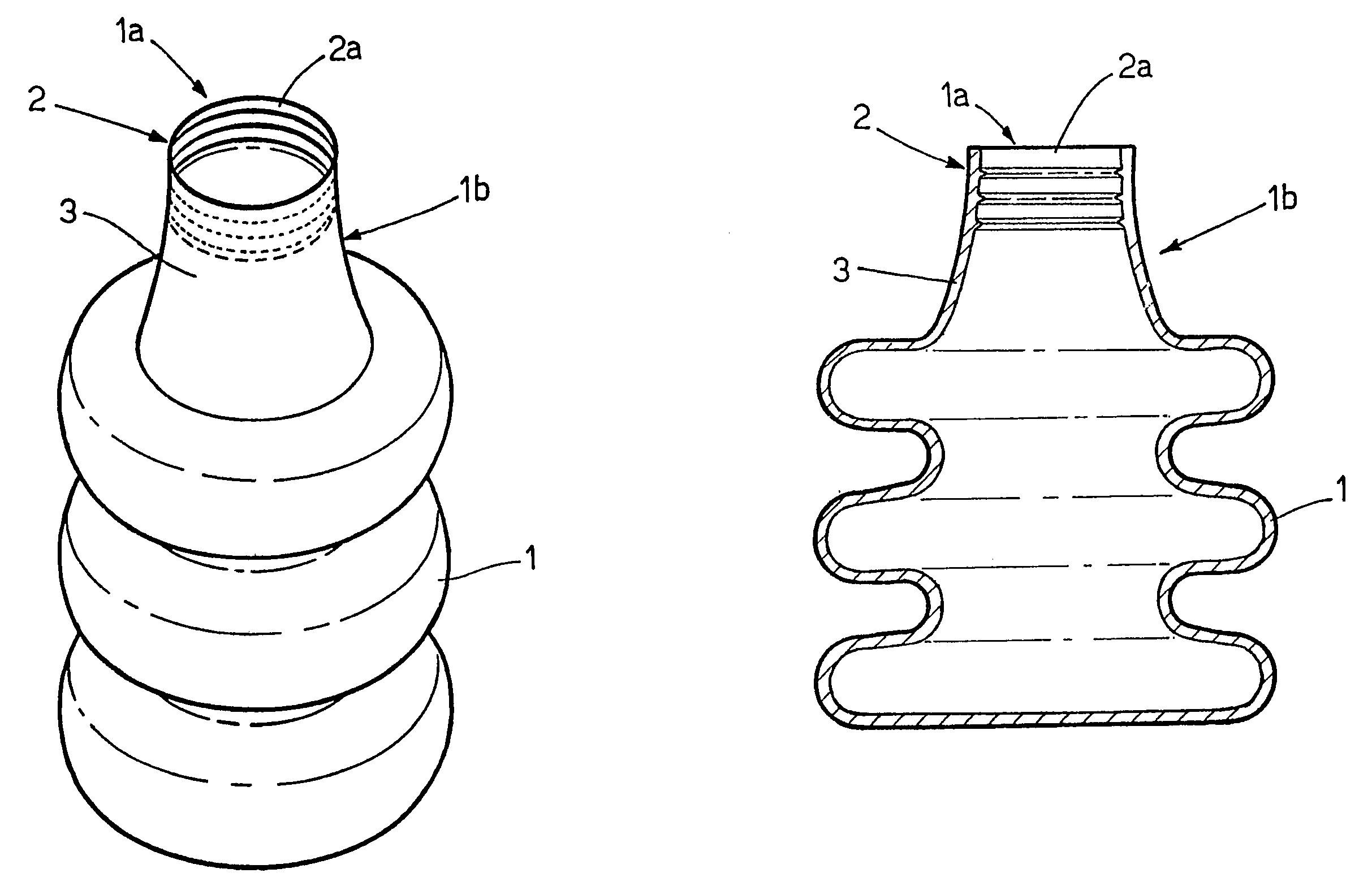
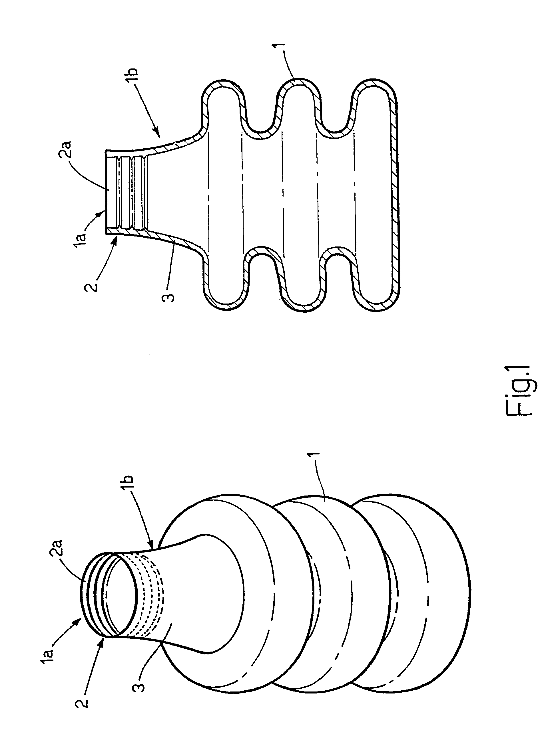
[0015]As can be seen from the figures, the present invention relates to a decorative glass for lamps; in addition to elements intended to distinguish it from an aesthetic point of view, and therefore extremely arbitrary and variable from one model to another, it comprises fastening means (2) which are formed as a single body and able to allow direct association with a lamp holder (P).

[0016]These fastening means (2) comprise a thread (2a) formed on the inner side of a surface portion (1a). Preferably, but not necessarily, the glass (1) comprises a fastening lug (1b) on which the abovementioned surface portion (1a) is located.

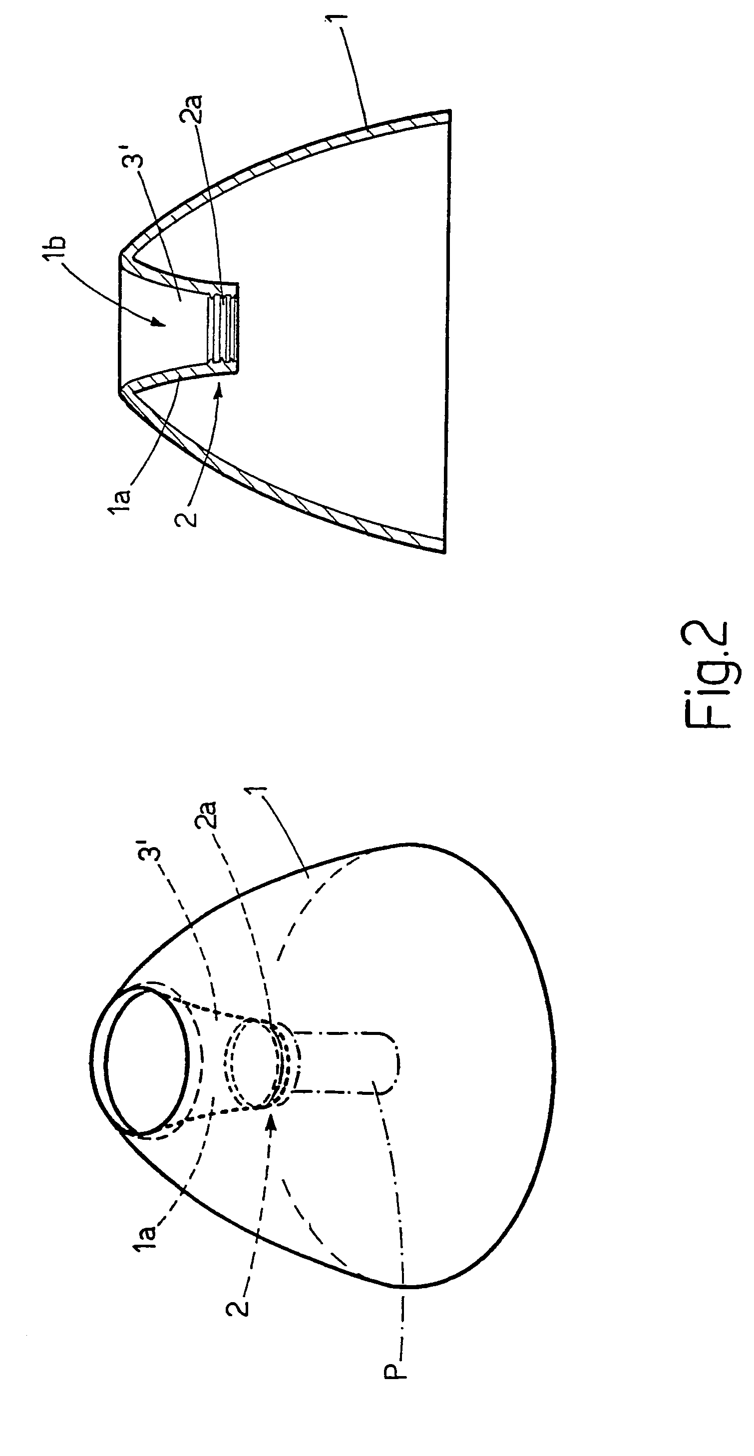
[0017]For example, as has been shown in the figures, but not in a limiting manner, the lug (1b) may consist of a neck (3) outside of the volume of the main body of the glass (1), as can be seen in FIG. 1, or also of a neck (3′) inside the volume of the main body of the glass (1), as can be seen in FIG. 2.

[0018]Since it is essential that the component used to manu...


PUM


Abstract

A decorative glass for lamps comprises a fastening device formed as a single body and able to allow direct association with a lamp holder. The fastening device preferably comprises a thread formed on the inner side of a surface portion of the glass.

Description

TECHNICAL FIELD[0001]The present invention relates to a decorative glass for lamps.BACKGROUND ART[0002]In the lighting technology sector it is very common to use decorative glass which, in addition to constituting an ornamental element influencing the aesthetic effect of the finished product, performs the dual function of ensuring improved diffusion of the light and protecting the light source which generally consists of a bulb.[0003]Many of the bulbs which are currently available are associated with lamp holders; however, the possibility of directly associating lamp holder and decorative glass does not exist.[0004]In fact, in the case where the glass has a thread, the latter is formed on a portion of their outer surface and, since the lamp holders may at best be also threaded externally, it becomes necessary to use an additional metal or plastic element which is machined internally and onto which the glass can be screwed or engaged in bayonet fashion. The limitation of this solutio...

Claims


Application Information

Patent Timeline
Patent Type & Authority Patents(United States)
IPC IPC(8): F21V3/00F21V3/04F21V17/06
CPCF21V3/00F21V17/06F21V3/04
Inventor ZANOTTI, MATTEO
Owner INTERLIGHTING AGENCY DI ZANOTTI MATTEO & C
Why Eureka
Try Eureka