Light emitting element and iridium complex

Active Publication Date: 2007-12-04
UDC IRELAND +1
View PDF15 Cites 2 Cited by
  • Summary
  • Abstract
  • Description
  • Claims
  • Application Information

AI Technical Summary

Benefits of technology

[0005]An object of the invention is to provide a light emitting element that can undergo light emission with

Problems solved by technology

However, since this element is still low in efficiency and is limited to green li

Method used


Image

  • Light emitting element and iridium complex
  • Light emitting element and iridium complex
  • Light emitting element and iridium complex

Examples


Example

Comparative Example 1

[0106]A washed ITO substrate was placed in a vapor deposition unit and vapor deposited with TPD (N,N′-diphenyl-N,N′-di-(m-tolyl)-benzidine) in a thickness of 50 nm. The following Compound A and Compound C were then vapor deposited thereon together in a ratio of 1:17 (weight ratio) in a thickness of 36 nm, and the following Azole Compound B was further vapor deposited thereon in a thickness of 36 nm. A patterned mask (a mask having a light emitting area of 4 mm×5 mm) was placed on the organic thin film, on which were then vapor deposited successively with lithium fluoride in a thickness of 3 nm and aluminum in a thickness of 60 nm, to prepare an element. Using a source measure unit, Model 2400 manufactured by Toyo Corporation, a DC regulated voltage was applied to the EL element to cause light emission, a luminance of which was then measured using a luminance meter, BM-8 manufactured by Topcon Corporation. As a result, green light emission with a maximum luminanc...

Example

Comparative Example 2

[0107]An element was prepared and evaluated in the same manner as in Comparative Example 1, except for using the following Compound E in place of the Compound A. Only feeble light emission was obtained from the element.

[0108]

Example

Example 1

[0109]An element was prepared and evaluated in the same manner as in Comparative Example 1, except for using Illustrative Compound (1-3) of the invention in place of the Compound A. As a result, brown light emission with a maximum luminance of 17,000 cd / m2 was obtained. A lowest drive voltage (a lowest voltage at which light emission can be visually confirmed) of the element was lowered by 1 V as compared with that of the element of Comparative Example 1.


PUM


Abstract

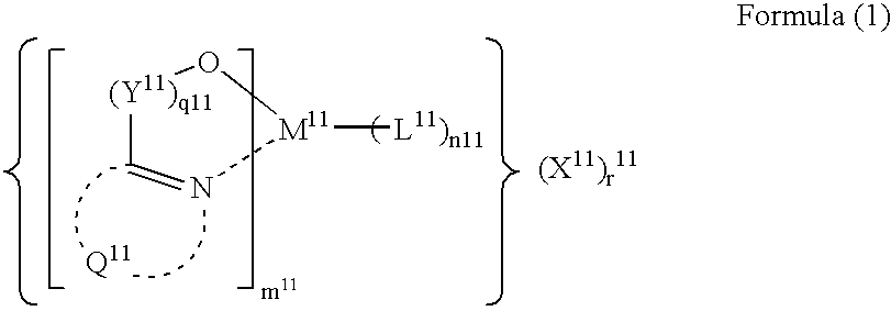
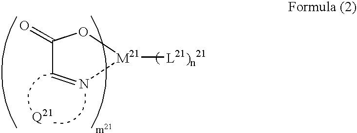
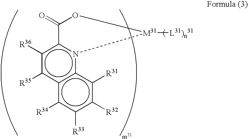
An organic electroluminescent element comprising: a pair of electrodes; and at least one organic layer provided between the pair of electrodes, at least one of the at least one organic layer being a light emitting layer, wherein the light emitting layer comprises at least one transition metal complex represented by the formula (1), (2), (3), (4) or (5) as defined herein or an iridium complex represented by the formula (A), (6), (7) or (8) as defined herein.

Description

FIELD OF THE INVENTION[0001]The present invention relates a light emitting element capable of converting an electric energy into a light to cause light emission. Also, the invention relates to a novel iridium complex that can suitably be used in the light emitting element. Especially, the light emitting element of the invention can suitably be utilized in organic electroluminescent (EL) elements.BACKGROUND OF THE INVENTION[0002]At present, research and development of various display elements are active. Especially, organic electroluminescent (EL) elements can obtain light emission with a high luminance at a low voltage, and therefore, are noticed as a promising display element.[0003]As measures for enhancing characteristics of light emitting elements, there is reported a green light emitting element utilizing light emission from an ortho-metalated iridium complex (Ir(ppy)3:Tris-Ortho-Metalated Complex of Iridium(III) with 2-Phenylpyridine) (see Applied Physics Letters, 75, 4 (1999))...

Claims


Application Information

Patent Timeline
IPC IPC(8): H01L51/54C07F15/00C09K11/06H01L51/00H01L51/30H01L51/50
CPCC07F15/0033H01L51/0085H01L51/0086C09K11/06Y10S428/917C09K2211/1003C09K2211/1007C09K2211/1011C09K2211/1014C09K2211/1029C09K2211/1033C09K2211/1037C09K2211/1044C09K2211/1092C09K2211/185C09K2211/188H01L51/0062H01L51/0081H01L51/50H10K85/649H10K85/344H10K85/324H10K85/342H10K50/00
Inventor IGARASHI, TATSUYAWATANABE, KOHSUKE
Owner UDC IRELAND
Why Eureka
Try Eureka