Biometric security assembly

a biometric and security technology, applied in the field of biometric security assembly, can solve the problems of increasing maintenance costs, affecting the security of the security system, and causing the loss of keys or duplicates,

Inactive Publication Date: 2007-12-04
MU HUA INVESTMENT
View PDF11 Cites 18 Cited by
  • Summary
  • Abstract
  • Description
  • Claims
  • Application Information

AI Technical Summary

Benefits of technology

[0023]Preferably, the receptor incorporates a first resistor such that the resistor limits the power supply to supply only power levels that will not damage the receptor circuit or the key circuit.
[0024]Preferably, the receptor incorporates a second resistor such that the resistor provides short circuit protection for the key circuit and / or the receptor circuit.

Problems solved by technology

Keys and locks are integral to most security systems but unfortunately, keys can be lost or duplicated and a security system can then be breached.
Electronic or electrically activated security assemblies often require a battery for their power source and this can be disadvantageous in that batteries require constant replacement and this increases maintenance costs.
This problem has been addressed to some extent for example in U.S. Pat. No. 5,337,588 by allowing insertion of the key in only one orientation which limits its utility and through elaborate electromechanical means to ensure that the contacts do not short out, which increases the cost of manufacture.

Method used


Image

  • Biometric security assembly
  • Biometric security assembly
  • Biometric security assembly

Examples


Embodiment Construction

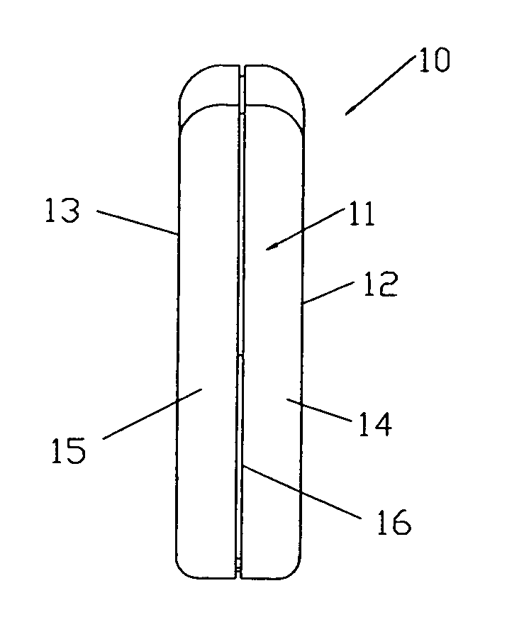
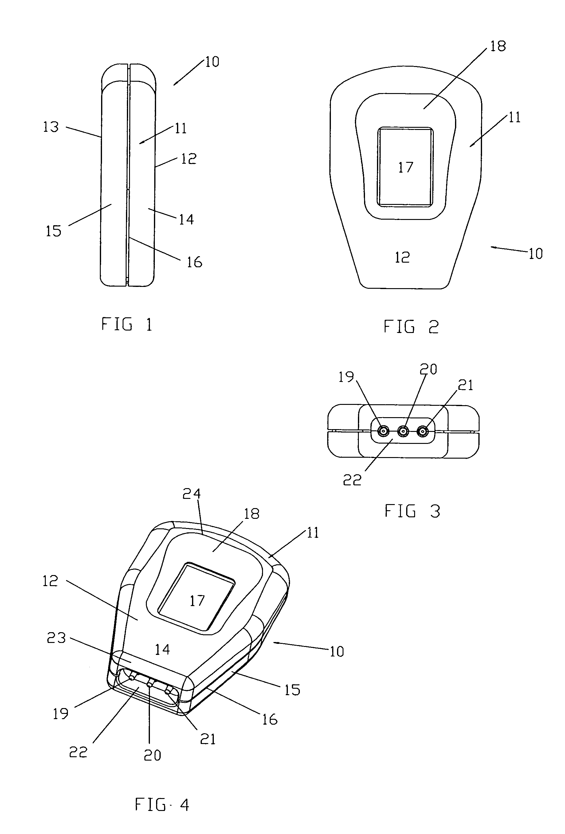
[0040]In the drawings in FIGS. 1 to 2 there is shown biometric key 10 having a body 11 having a front surface 12 and a rear surface 13. There is also shown a top component 14 in use and lower component 15 in use which are both attached to each other at a point 16. The front surface 12 includes a sensor 17 surrounded by a recess 18.

[0041]In FIGS. 3 to 4 there is shown contact pins 19, 20 and 21 located in cavity 22 located at one end 23 of key 10 which is narrower in width than the other end 24.

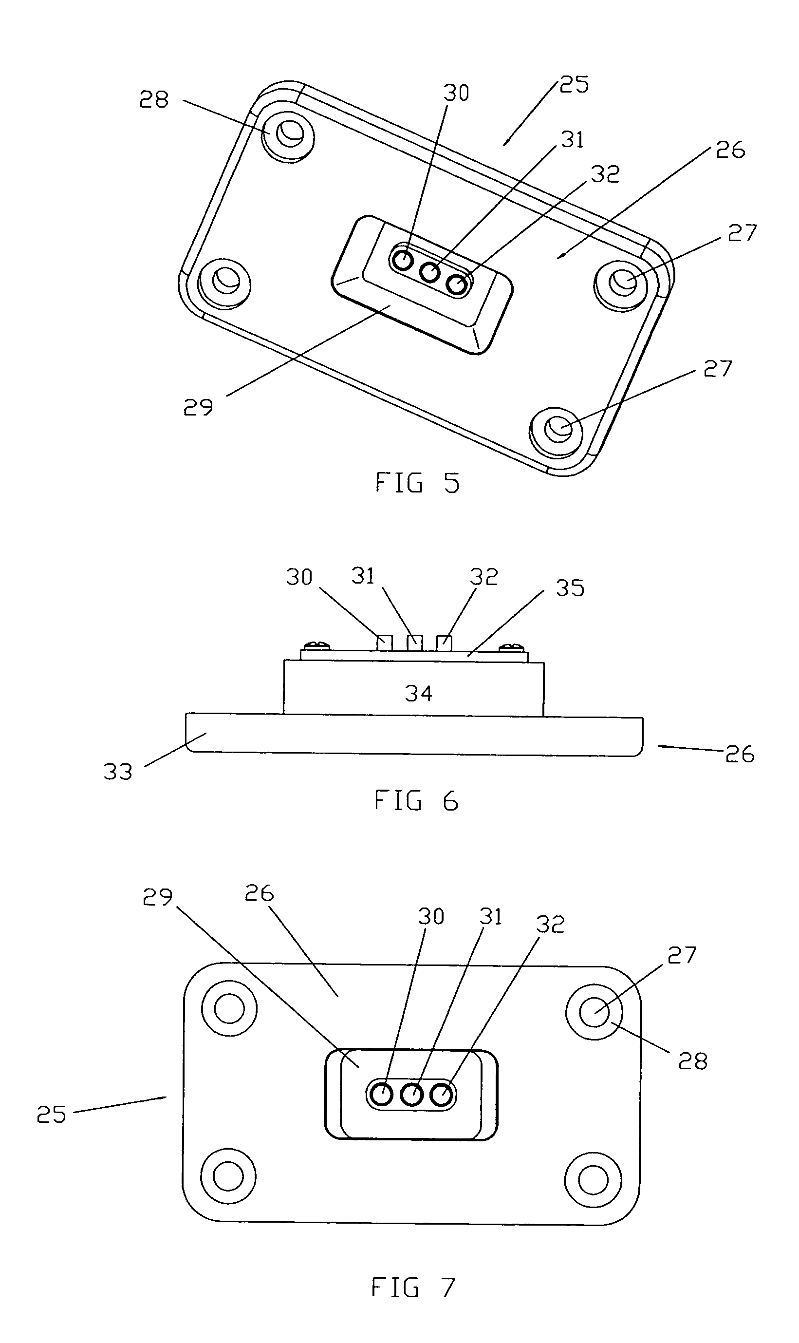
[0042]In FIGS. 5 to 7 there is shown door controller receptor 25 having a plate like body 26 and attachment apertures 27 for attachment to a door (not shown). There is also shown recesses 28 for the head (not shown) of fasteners (not shown). The door controller receptor 25 is provided with a central hollow 29 and there are also provided stationary contacts 30, 31 and 32 which abut each spring loaded pins 19, 20 and 21 in use. Body 26 includes an attachment part 33 and an adjacent part 34 surro...


PUM


Abstract

A biometric key (10) having a body or housing (11) incorporating a biometric sensor (17) uses a plurality of contacts (19, 20, 21) enabling the key to gain access to a facility. There is also provided a receptor (25) for receiving the biometric key (10), wherein the biometric key (10) and receptor (24) have contacts (19, 20, 21) and mating contacts (30, 31, 32), respectively, for communicating. The biometric key (10) can communicate biometric data acquired from a key operator to the receptor (25). The biometric key (10) can communicate with the receptor (25) when received in a first orientation and also when received in a second orientation where the contacts (19, 20, 21) are inverted from the first orientation.

Description

FIELD OF THE INVENTION[0001]This invention relates to a biometric security assembly for providing access to a facility.BACKGROUND TO THE INVENTION[0002]Security systems are relied upon to secure environments and possessions such as cars, homes, businesses and prisons. Keys and locks are integral to most security systems but unfortunately, keys can be lost or duplicated and a security system can then be breached.[0003]Electronic or electrically activated security assemblies often require a battery for their power source and this can be disadvantageous in that batteries require constant replacement and this increases maintenance costs.[0004]To overcome the disadvantages of conventional lock and key systems as described above a conventional biometric security assembly has been developed that reads biometric data from an operator in order to verify the operator's identity.[0005]A biometric security assembly which includes a biometric key and lock for engagement with the key is described...

Claims


Application Information

Patent Timeline
Patent Type & Authority Patents(United States)
IPC IPC(8): G06F7/40G06F7/20E05B49/02G07C9/00H04K1/00
CPCG07C9/00563G07C9/00309G07C2009/00761G07C2009/00095G07C9/00944G07C9/26
Inventor BACCHIAZ, JOHN DAVIDBRUNELL, DAVID
Owner MU HUA INVESTMENT
Why Eureka
Try Eureka