Roller/foot device castor

a technology of a foot device and a roller body, which is applied in the direction of castors, vehicle components, multi-purpose tools, etc., can solve the problems of reducing the movement capacity of furniture, the device is not equipped with means or arrangements for securing the roller body, and the insufficient capacity of the roller device to equip it with ordinary brake means, etc., to achieve easy marking or scratching

Active Publication Date: 2007-12-11
WHEEL ME AS
View PDF20 Cites 24 Cited by
  • Summary
  • Abstract
  • Description
  • Claims
  • Application Information

AI Technical Summary

Benefits of technology

[0031]When using surfaces which are easily marked or scratched, the outer edge of the outer sleeve may be protected by a pad of a suitable material such as foam, plastic, felt or the like. The pad will preferably be doughnut-shaped with an ou

Problems solved by technology

Particularly when using roller devices on objects where a high degree of stability is required, and especially where the objects in themselves are heavy or are carriers of heavy and/or unstable loads, it will often not be sufficient to equip the roller device with ordinary brake means.
In the solution disclosed in DE 198 01 509 the device is not equipped with means or arrangements for securing the roller body in the rolling position.
A drawback of the solution discl

Method used


Image

  • Roller/foot device castor
  • Roller/foot device castor
  • Roller/foot device castor

Examples


Embodiment Construction

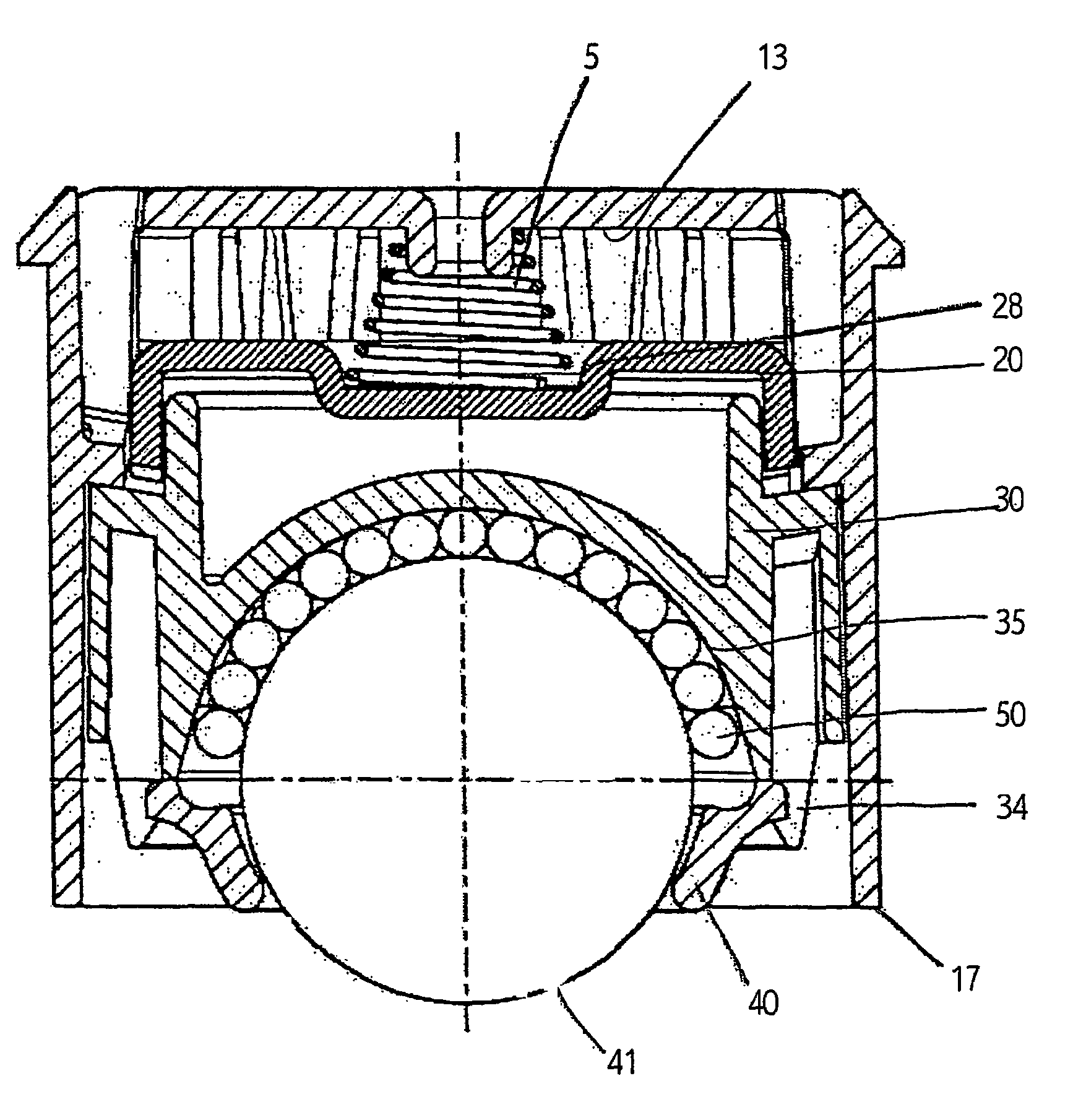
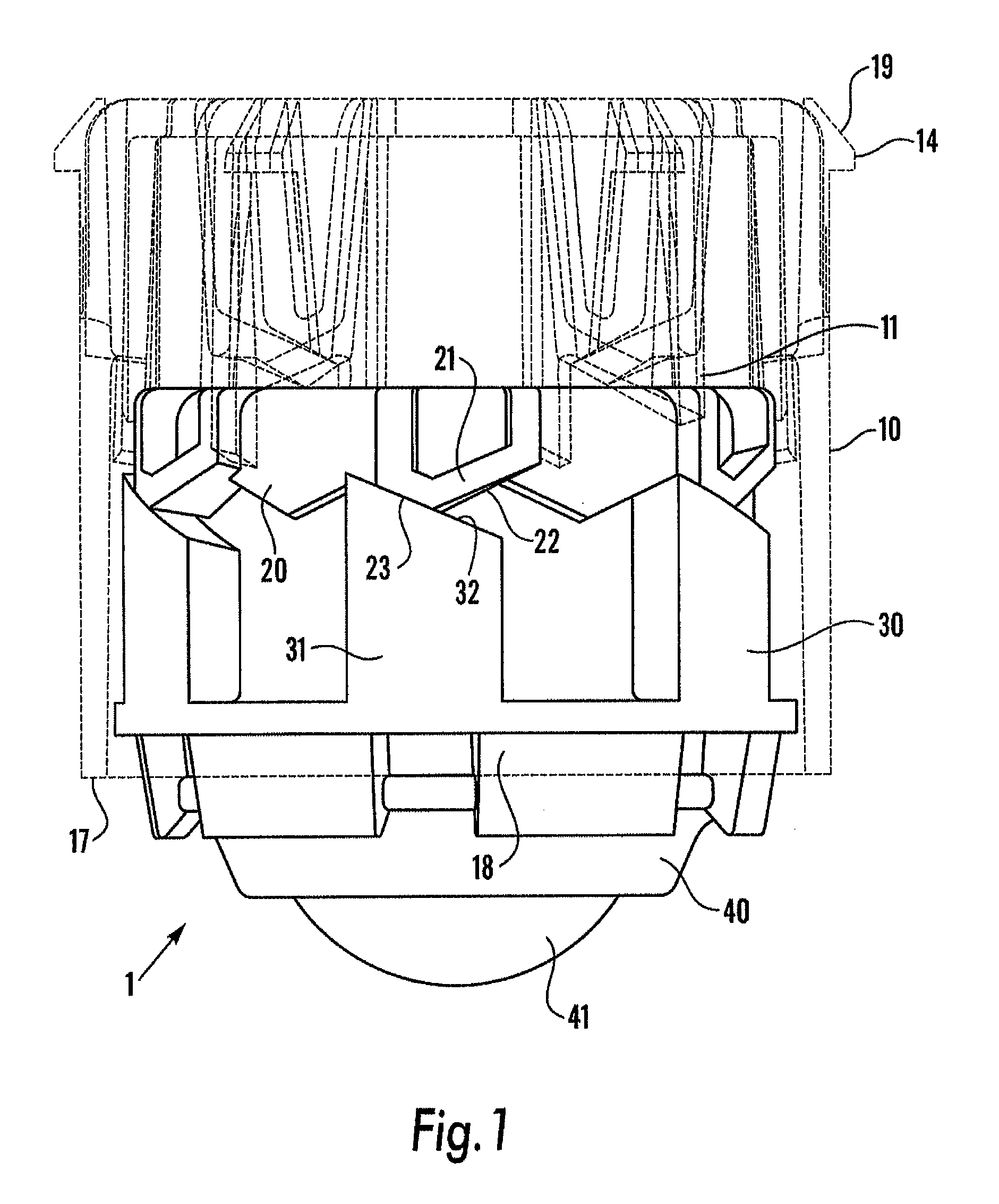
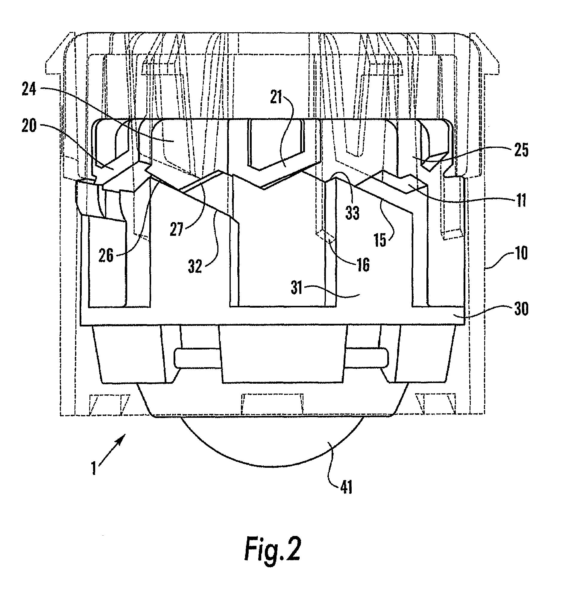
[0038]FIG. 1 illustrates the device 1 according to the invention with no forces acting inwards in the outer sleeve 10. In this embodiment the roller element is a ball 41. In FIG. 1 the ball is kept in its outermost position in the outer sleeve 10 by the force from the spring device (not shown). The spring device presses the guide sleeve 20 outwards towards the outer sleeve's 10 open end 17. The ribs 21 on the guide sleeve slide in the grooves between the outer sleeve's ribs 11. The end surfaces (22,23) of the ribs 21 on the guide sleeve abut against the end surface 32 of the ribs 31 on the locking sleeve 30, and the locking sleeve 30 and thereby the ball 41 are thereby also pressed outwards towards the outer sleeve's 10 open end 17. In this embodiment the outer sleeve 10 has outwardly protruding edge pieces 18 which prevent the locking sleeve 30 and the guide sleeve 20 from being pushed out of the outer sleeve 10.

[0039]The ball 41 is attached against the locking sleeve 30 by means o...


PUM


Abstract

A roller/foot device (1) comprising a cylindrical outer sleeve (10), a guide sleeve (20) arranged inside the outer sleeve (10), locking sleeve (30) arranged inside the outer sleeve (10), a spring device where one end abuts against the outer sleeve's closed end (13) and the other end abuts against one end portion of the guide sleeve or the locking sleeve and a roller element (41) which is rotatably mounted abutting against the locking sleeve's (20) end portion which is located at the extreme end of the outer sleeve (10). The sleeves comprise ribs which can slide towards each other and cause the roller element (41) to assume different positions in the longitudinal direction of the outer sleeve (10) when the device (1) is subjected to forces. The device (1) can thereby be employed as a roller device with the roller element (41) in an outer position and as a foot device with the roller element (41) in an inner position.

Description

[0001]This application claims the benefit under 35 USC §119(e) to U.S. Provisional Application 60 / 399,137 filed, 30 Jul. 2002.FIELD OF THE INVENTION[0002]The present invention relates to a device for moving an object by means of a roller device which can be concealed in a sleeve body.BACKGROUND OF THE INVENTION[0003]Roller devices are often employed when moving objects in order to reduce the load and facilitate maneuvering. The roller devices may be directly attached to the object that has to be moved, either releasably or as an integrated part of the object. The object may also be placed on a support unit equipped with roller devices. Objects and support units equipped with roller devices and used for moving objects are often also required to be capable of assuming a stationary position.[0004]One solution for achieving such a position will be to equip the roller devices with brake means. Particularly when using roller devices on objects where a high degree of stability is required,...

Claims


Application Information

Patent Timeline
IPC IPC(8): B60B33/00B60B33/06F16C
CPCB60B33/08Y10T16/195Y10T16/1867
Inventor LIBAKKEN, ROLF
Owner WHEEL ME AS
Why Eureka
Try Eureka