Tip rod

a tip rod and rod body technology, applied in the field of tip rods, can solve the problems of difficult to approximate the elongation percentage, difficulty in giving an oval shape of solid materials, and difficulty in bending fishing rods, and achieve the effect of preventing loose screws and reducing breakag

Active Publication Date: 2007-12-11
DAIWA SEIKO CORPORATION
View PDF16 Cites 17 Cited by
  • Summary
  • Abstract
  • Description
  • Claims
  • Application Information

AI Technical Summary

Benefits of technology

[0010]Another object of the invention is to provide a high-quality tip rod for raft fishing which is slight in bending and stable in strength.
[0054]The presence of the tapered part on the cylinder side makes it easy to introduce the rear part of the solid member into the cylindrical component. Further, since the front side part can be gradually larger in diameter than the part of the male screws of the solid member, the tip rod can be rendered to be difficult in breakage. In addition, since the cylinder side tapered part is formed in taper ratio greater than that of the tapered part on the cylinder side, the surface of the cylinder side tapered part comes in contact with the tip part of the tapered part on the cylinder side, tightens gradually, thereby preventing loose screws, when screwed together.

Problems solved by technology

However, super-elastic alloys are 3 to 8% in elongation, and glass fibers, a low-elastic material and also a high elongation percentage material, are 3.5 to 4% in elongation, thus making it difficult to approximate the elongation percentage.
A tubular member tends to give an oval shape when the transverse section is deformed on the substantial bend of the rod, whereas a solid material will be difficult in giving an oval shape.
When a prepreg sheet or a tightening tape is made greater in tensile force for preventing inclusion of bubbles in manufacturing a particularly slender fishing rod such as a tip rod, the force may deflect fishing rod materials thus resulting in a problem of bent fishing rods.
Further even if the deflection is not observed before the burning, deflection may occur due to internal stress during heating and burning.
Deflected fishing rods are defective and result in a lower yield.
In this connection, where a fiber-reinforced resin part is directly provided with screws as disclosed in the patent document 2, there is a problem that screw threads are fragile.
Further, particularly in a case where a slender cylindrical fishing rod body is provided with screws, stress will concentrate on the part of screws, thus posing another problem.
In this instance, a slender cylindrical fishing rod body made with a fiber-reinforced resin will easily develop cracks by processing pressure.

Method used


Image

  • Tip rod
  • Tip rod
  • Tip rod

Examples


first embodiment

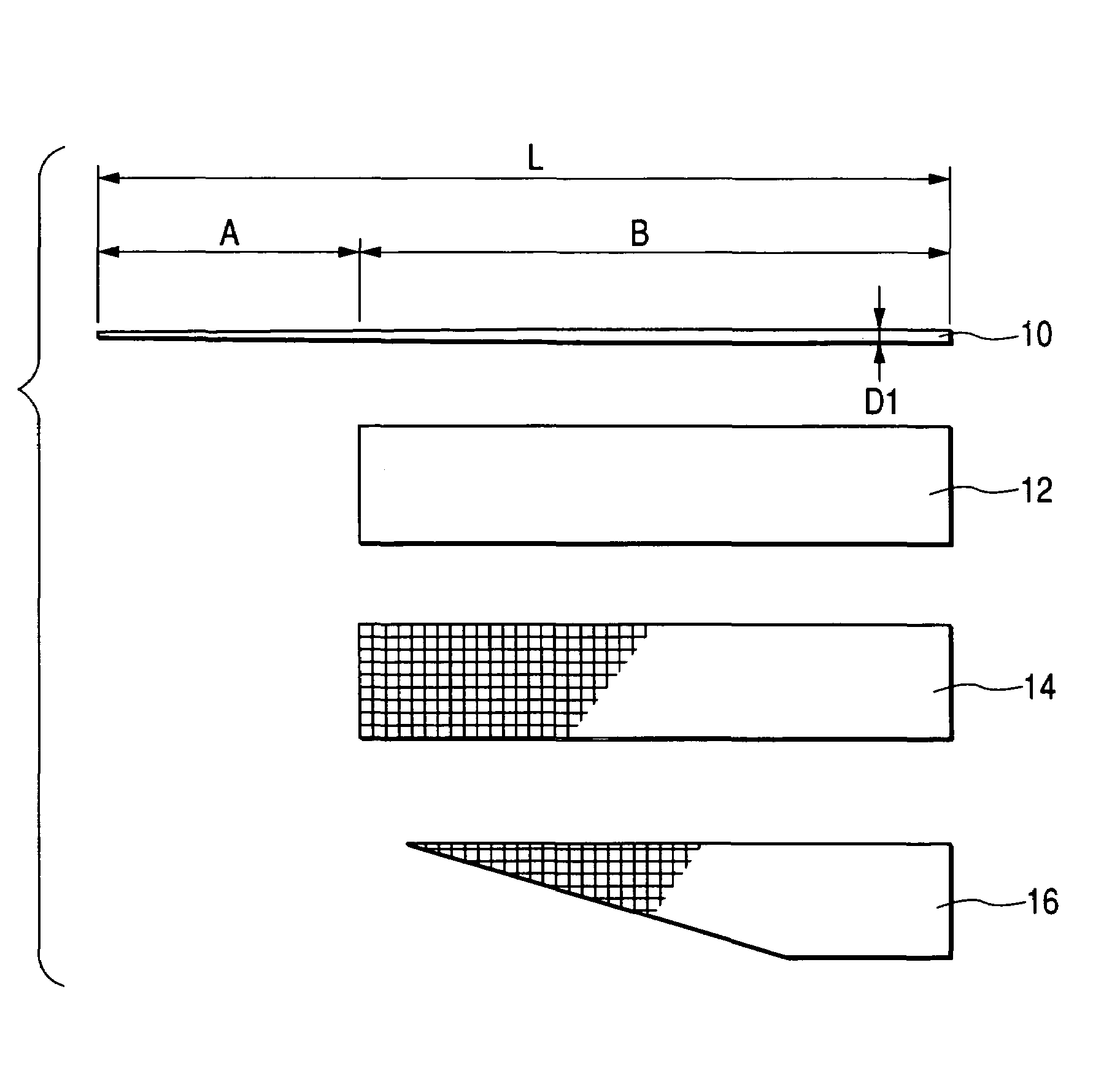
[0063]FIG. 1 is a drawing explaining a method for manufacturing the tip rod according to a first embodiment of the invention. Of previously-explained examples of super-elastic alloys, in this embodiment, the solid core material 10 made with an Ni—Ti alloy is 530 mm in length L, and the tip part region A is in a tapered shape, with the diameter at the tip end about 0.3 mm. In general, the diameter is preferably in a range from 0.2 to 0.3 mm to provide delicateness. The rest of the rear part region B is straight and about 1.1 mm in diameter D1. The rectangular resin sheet 12 along almost the entire length of the rear part region B and the similar-sized prepreg sheet 14 made with a glass fiber woven textile are super imposed and wound up together. The resin used in this resin sheet is epoxy resin, as with that used in the sheet 14 or the sheet 16 to be explained later. The resin sheet 12 is 13 microns in thickness and the prepreg sheet 14 is about 17 microns, and will be wound around, ...

second embodiment

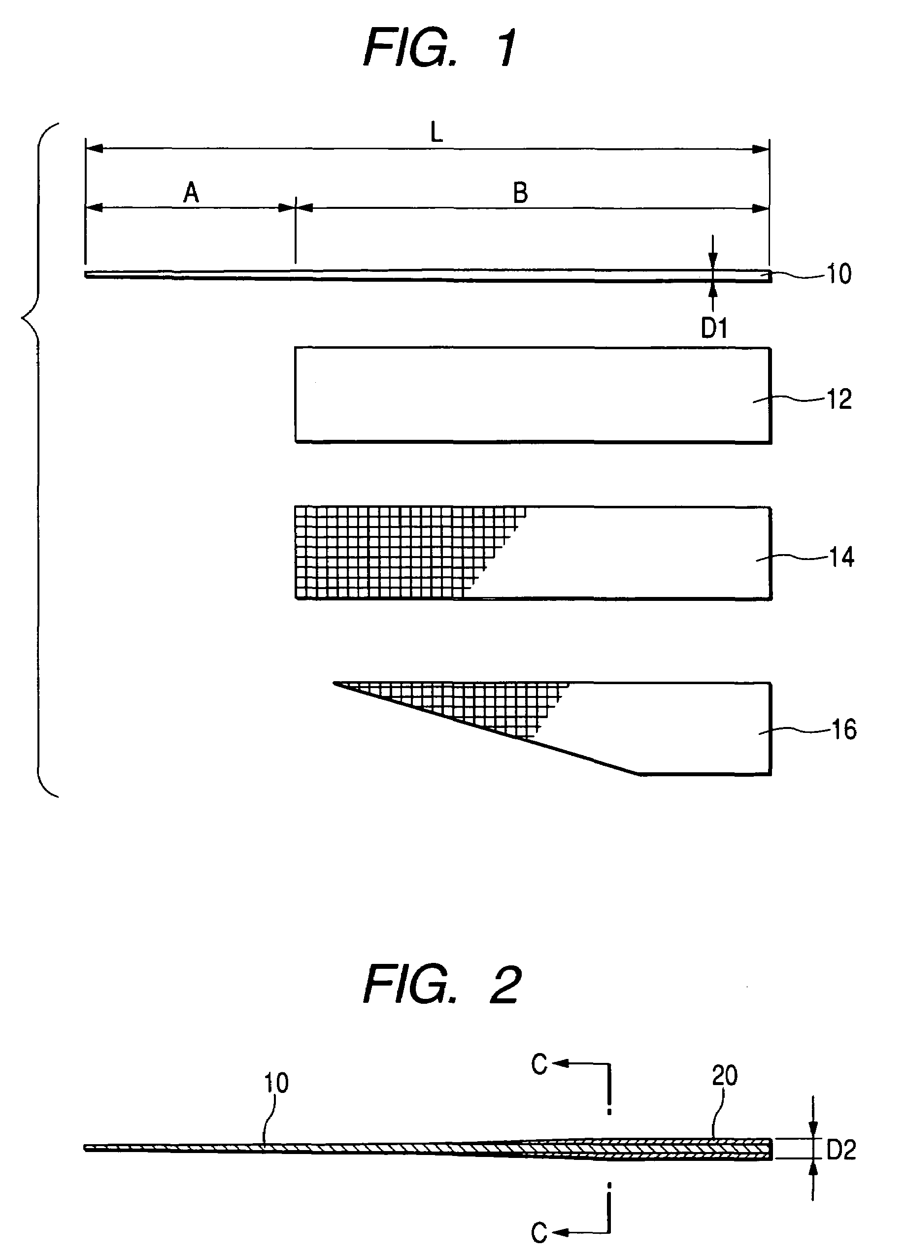
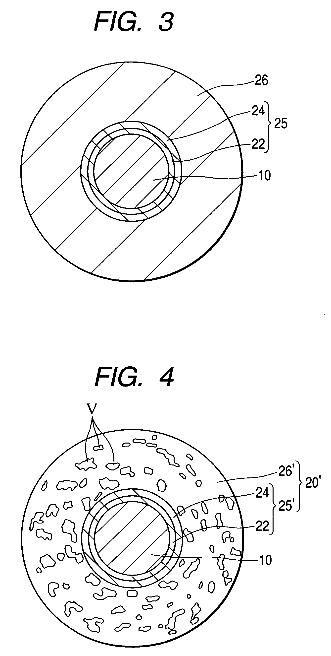
[0068]Next, an explanation will be made for a second embodiment of the invention. This embodiment is different from the first embodiment in constitution of an additionally reinforced resin region (layer). Since remaining constitution are the same as the first embodiment, the same symbols are given and the explanation will be omitted. FIG. 4 is an enlarged transverse cross sectional view of the tip rod, when viewed from the arrow line C-C in FIG. 2 according to a second embodiment.

[0069]Observation of the cross section reveals a plurality of bubbles V on the outside layer 26′ formed by the prepreg sheet 16, as shown in FIG. 4. In this instance, the bubbles are found only on the layer 26′ in the body but they could be produced on the resin-rich layer 25′ as well, although small in number. In other words, the bubbles could be dispersed in the fiber-reinforced resin region (layer) 20′ which combines the resin-rich layer 25′ and the outside layer 26′. The bubbles are mostly found in size...

third embodiment

[0072]FIG. 5 is a longitudinal sectional view of the tip rod according to a third embodiment of the invention. About half of the front side of the tip rod is the solid member 110 made with an Ni—Ti alloy of the previously-described super-elastic alloys, having a matrix as synthetic resins such as epoxy resin at the rear end part and joining with the tubular member 112 made with a fiber-reinforced resin strengthened with reinforced fibers such as carbon fibers and glass fibers. FIG. 6 is an enlarged view of the joining part of the tip rod and the vicinity. The cylindrical component 114 made with a metal such as stainless steel or brass is pressure-fitted and adhered to the inner surface 112A at the front end part of the tubular member 112, and female screws are provided on the inner surface of the cylindrical part. The outer circumferential surface of this cylindrical part is formed in a fine irregularity polished with sandpaper (No. 100 to No. 600), and the inner surface at the fron...


PUM

PropertyMeasurementUnit
roughnessaaaaaaaaaa
thicknessaaaaaaaaaa
thicknessaaaaaaaaaa

Abstract

Where a super-elastic alloy is used as a core material, boundary separation can be prevented on substantial deflection. The super-elastic alloy is used as the core material, an outside layer made with fiber-reinforced resin is provided outside except the tip part region of the core material, and a resin-rich layer greater in resin ratio than the outside layer is provided between the outside layer and the core material so as to be adjacent to the core material.

Description

BACKGROUND OF THE INVENTION[0001]The present invention relates to a tip rod in which a super-elastic alloy is used. Accordingly, the rod is applicable for a fishing rod, especially for “a fishing rod used in raft fishing” for catching black porgy and etc, and for a fishing rod for catching filefish and etc.[0002]A fishing rod to be used in catching black porgy etc., on a raft is made short in length and light in weight. It is, for example, from 1.3 to 2.1 meters in entire length. It is also made particularly slender in the rod tip part so as to respond delicately. Tip rods to be used in raft fishing are manufactured on the premise that they are bent substantially. Patent document 1 listed below has disclosed a fishing rod provided with a layer of a fiber-reinforced resin made with a low-elastic material or a high elongation percentage material adjacent to a core material of a super-elastic alloy and also provided with a layer of a high-elastic and low-elongation percentage material ...

Claims


Application Information

Patent Timeline
Patent Type & Authority Patents(United States)
IPC IPC(8): A01K87/00
CPCA01K87/00
Inventor KATO, YOSHINAOOHTSU, TAKENORINAITO, HIDEYUKIAKUTSU, TETSUOOIKAWA, KATSUHIROKOSAI, HIDENORI
Owner DAIWA SEIKO CORPORATION
Why Eureka
Try Eureka