Method and apparatus for phased array based ultrasonic evaluation of rail

a phased array and ultrasonic evaluation technology, applied in the direction of instruments, specific gravity measurement, heat measurement, etc., can solve the problems of horizontal defects, transverse defects and bolthole defects, bolthole defects, horizontal and transverse defects, bolthole defects, etc., to achieve the effect of reducing the fatigue of cyclic us

Active Publication Date: 2007-12-11
PROGRESS RAIL SERVICES
View PDF10 Cites 28 Cited by
  • Summary
  • Abstract
  • Description
  • Claims
  • Application Information

AI Technical Summary

Benefits of technology

[0008]In accordance with another embodiment of the present technique, an exemplary method for testing material integrity of an object is provided. The method includes controlling a first aperture dynamically for transmitting a first set of ultrasonic signals towards a region of interest. The method further includes controlling a second aperture dynamically to receive a second set of ultrasonic signals from the region of interest. Advantageously, the use of dynamic apertures facilitates increases in testing speeds and, as such, facilitates improved testing.

Problems solved by technology

By way of example, commonly occurring defects in the rail and / or railheads of railroad transportation systems are horizontal defects, transverse defects and bolthole defects.
Another general category of defects is bolthole defects, which generally occur near the boltholes of the rail.
Under certain conditions, horizontal and transverse defects as well as bolthole defects can propagate under the fatigue of cyclic use.
Unfortunately, these defects or cracks in the rail can increase the likelihood of failure or malfunction of the rail and / or railhead, leading to undesirable maintenance costs and downtimes, for instance.
That is to say, if scan speeds exceed 35 mph, losses of reflected ultrasonic signals will dramatically increase, because the ultrasonic transducers will have traveled past the inspection area before the reflected ultrasonic signals can reach or return to the transducer.
Hence, traditional testing techniques are limited at the speed at which testing can be performed.
Unfortunately, limited testing speeds can lead to unwanted delays in track testing that, in turn, can lead to track closures, for instance.
Unfortunately, angularly maintaining the ultrasonic transducers with respect to the rail decreases the cross-section coverage area of the ultrasonic transducers.

Method used


Image

  • Method and apparatus for phased array based ultrasonic evaluation of rail
  • Method and apparatus for phased array based ultrasonic evaluation of rail
  • Method and apparatus for phased array based ultrasonic evaluation of rail

Examples


Embodiment Construction

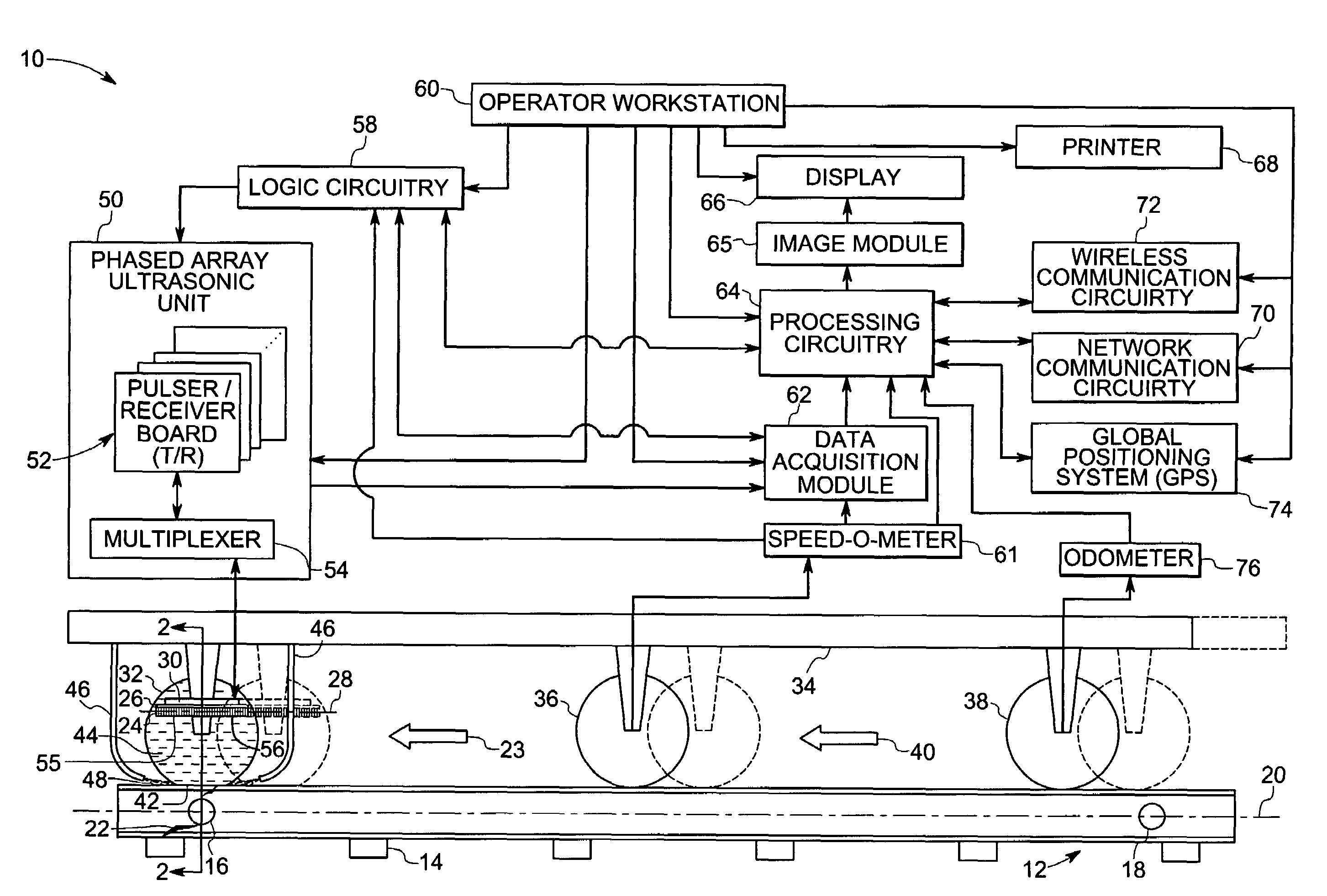
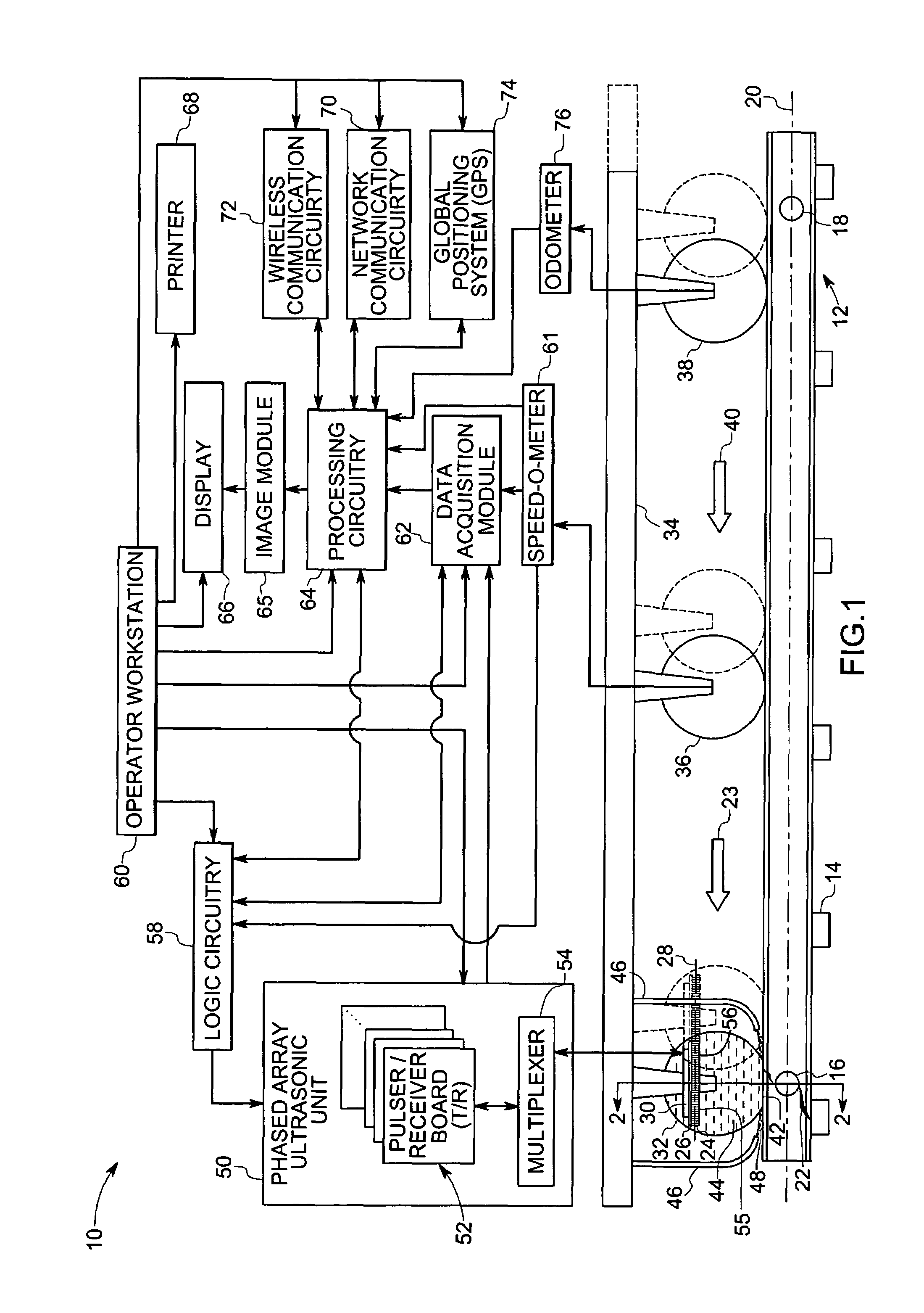
[0021]The present technique is directed towards testing the integrity of an object and for detecting defects in the object. Although following discussion focuses on testing apparatus and methods for rails in railroads using phased array transducers, those skilled in the art will recognize in light of the following discussion that the present technique is applicable to a wide variety of testing environments and settings. For example, the present technique can be applied for testing of plates, bars and support structures, to name but a few applications. These techniques utilize transmitting ultrasonic signals into the object, receiving reflected ultrasonic signals from the object and analyzing the received ultrasonic signals for determining defects in the object. Furthermore, the following discussion merely present exemplary embodiments of the present technique, and is not intended to limit the scope of the appended claims to the discussed embodiments.

[0022]As a preliminary matter, th...


PUM

PropertyMeasurementUnit
timeaaaaaaaaaa
speedaaaaaaaaaa
speedsaaaaaaaaaa

Abstract

In accordance with one embodiment, the present technique provides a testing apparatus for testing material integrity of an object. The exemplary testing apparatus includes a phased array transducer, which is disposed external to the object. The phased array transducer is configured to transmit a first set of ultrasonic signals and to receive a second set of ultrasonic signals. The testing apparatus further includes logic circuitry coupled to the phased array transducer. The logic circuitry is configured to dynamically control apertures for transmitting the first set of ultrasonic signals and receiving the second set of ultrasonic signals based on a region of interest and a testing speed.

Description

BACKGROUND[0001]The present invention relates generally to a technique for inspecting materials and testing material integrity. Particularly, the present technique relates to methods and apparatus for testing the integrity of rails in railroad systems using phased array based ultrasonic techniques.[0002]Detecting the presence of defects in rails can assist maintenance technicians, for example, in predicting and mitigating the likelihood of rail malfunctions due to defects, for instance. By way of example, commonly occurring defects in the rail and / or railheads of railroad transportation systems are horizontal defects, transverse defects and bolthole defects. Horizontal defects, such as shelling and horizontal split-heads, are generally transverse and sometimes parallel to the longitudinal axis of the rail. Conversely, transverse defects are generally perpendicular to the longitudinal axis of the rail. Another general category of defects is bolthole defects, which generally occur nea...

Claims


Application Information

Patent Timeline
Patent Type & Authority Patents(United States)
IPC IPC(8): G01N29/06G01N29/265
CPCB61K9/10G01N29/043G01N29/262G01N2291/02854G01N2291/2623G01N2291/0428G01N2291/044G01N2291/106G01N2291/0422
Inventor BARSHINGER, JAMES NORMANDEWANGAN, SANDEEP KUMARRAMASWAMY, SIVARAMANIVASLI, JIAN
Owner PROGRESS RAIL SERVICES
Why Eureka
Try Eureka