Method for testing geometric parameters of optical fiber coating layers

A technology of geometric parameters and detection methods, applied in measurement devices, optical devices, instruments, etc., can solve the problems of inability to meet the requirements of optical fiber manufacturers, poor test stability performance, and low test accuracy, and improve test speed and test accuracy. Accuracy, improved test speed, wide application effect

Active Publication Date: 2013-05-22
SHANGHAI SECRI OPTICAL & ELECTRIC CABLE CO LTD
View PDF3 Cites 16 Cited by
  • Summary
  • Abstract
  • Description
  • Claims
  • Application Information

AI Technical Summary

Problems solved by technology

[0006] i. Low test accuracy;
[0007] ii. There are few test parameters, which cannot meet the requirements of optical fiber manufacturers;
[0008] iii. Poor test stability

Method used


Image

  • Method for testing geometric parameters of optical fiber coating layers
  • Method for testing geometric parameters of optical fiber coating layers
  • Method for testing geometric parameters of optical fiber coating layers

Examples


Embodiment 1

[0061] Test the parameters of the optical fiber through the following steps:

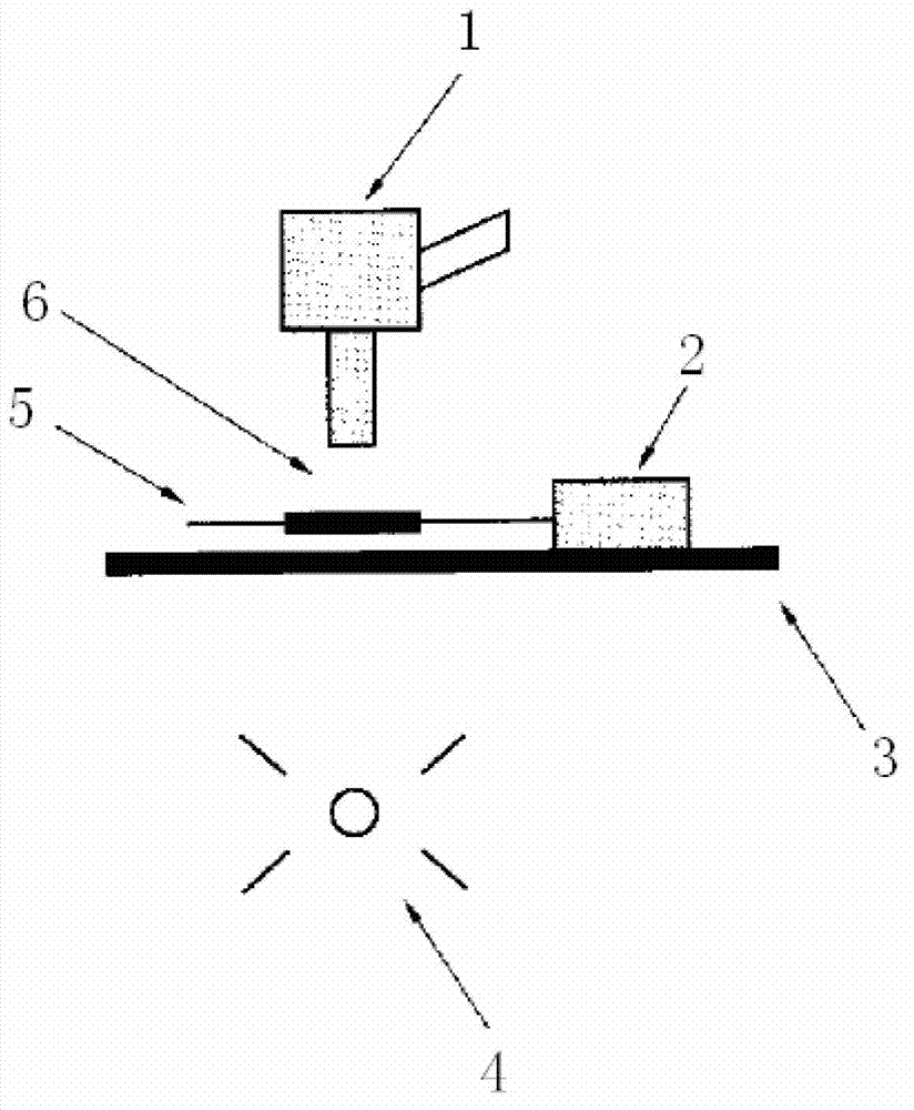
[0062] (1) Peel off the coating layer after the end face of the optical fiber coating layer, and then use a light source to illuminate from the stripped place;

[0063](2) The light source passes through the conduction of the coating layer to illuminate the end face of the fiber coating layer;

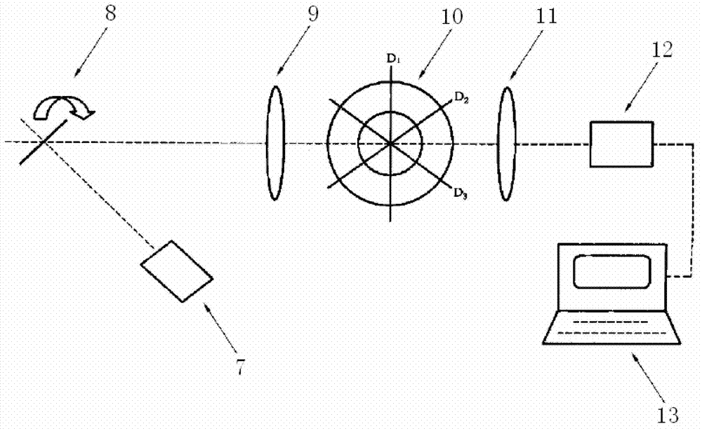
[0064] (3) Project the image of the end face of the optical fiber coating to the CCD imaging system, and the image acquisition system collects the image,

[0065] Through the different material attenuation coefficients of each coating layer and different light incident angles, each layer can be distinguished, and then the coating diameter and coating layer of each coating layer of the optical fiber coating layer can be calculated through the image processing system. Coating out-of-roundness, minimum (maximum) coating thickness, coating\core concentricity error and other parameters.

[0066] The design spec...


PUM


Abstract

The invention relates to the field of optical fiber coating, in particular to a method for testing geometric parameters of optical fiber coating layers. The method for testing the geometric parameters of the optical fiber coating layers includes the steps: stripping each coating layer from the end face of each optical fiber coating layer to the rear by a proper length and irradiating into the coating layer from a stripped position by a light source; conducting the light source by the coating layer and lighting up the end face of each optical fiber coating layer; and projecting images of the end faces of the optical fiber coating layers into an imaging system. The layers can be distinguished according to different attenuation coefficients of materials of the coating layers and different angles of light incidence. The geometric parameters of the end faces of the optical fiber coating layers are tested by the method, the testing speed and the testing accuracy of a geometric parameter tester for the optical fiber coating layers are greatly improved, and the testing accuracy of the geometric parameters of the primary coating layer is particularly improved.

Description

technical field [0001] The invention relates to the field of optical fiber coating, in particular to a method for detecting geometric parameters of optical fiber coating layers. Background technique [0002] Existing testing methods for measuring the optical fiber coating include a side-view light distribution method and a mechanical method to measure the size of the optical fiber coating layer on the side of the optical fiber. [0003] A. Side-view method: use a suitable fiber optic fixture to rotate the fiber sample, measure the cladding diameter, primary coating diameter, and secondary coating diameter at different angle positions, and calculate the maximum and minimum values ​​of the corresponding parameters. Test device such as figure 1 and figure 2 shown. Such as figure 1 and figure 2 The side view method shown is to test the geometric dimensions of the optical fiber coating layer on the side of the optical fiber. Since the optical fiber itself is transparent an...

Claims


Application Information

Patent Timeline
Patent Type & Authority Applications(China)
IPC IPC(8): G01B11/00G01B11/08G01B11/24G01B11/06G01B11/26
Inventor 沈奶连涂建坤王建财
Owner SHANGHAI SECRI OPTICAL & ELECTRIC CABLE CO LTD
Why Eureka
Try Eureka