Two-step roller finger follower

a roller finger follower and roller finger technology, applied in the direction of mechanical control devices, instruments, process and machine control, etc., can solve the problems of hla leakage, excessive variation in the installed load, etc., and achieve high stability and predictable spring rate

Active Publication Date: 2007-12-11
DELPHI TECH IP LTD
View PDF12 Cites 72 Cited by
  • Summary
  • Abstract
  • Description
  • Claims
  • Application Information

AI Technical Summary

Benefits of technology

[0008]Briefly described, a two-step roller finger follower in accordance with the invention includes a high-lift follower portion that rotates relative to a low-lift follower portion about a pivot shaft. A lost-motion compression spring is disposed in a linear bore formed in the high-lift portion and exerts force against a radiused pad on the back side of the valve pallet of the low-lift portion. The spring is retained and guided in its bore by a spring retainer having a planar bottom for engaging the radiused pad. In an alternate embodiment the retainer is a cup positioned in the spring bore such that the stroke of the cup is limited to prevent load from being applied on the hydraulic lash adjuster when the cam is on base circle. Driving the spring by a linear-acting retainer in a linear bore causes the spring to be compressed linearly, resulting in a highly stable and predictable spring rate.

Problems solved by technology

If the force of the lost motion spring is too small, the high-lift follower may not be able to stay in contact with the cam under all engine operating conditions.
If the spring force is too large, the force of the lost motion spring may overcome the force of the internal spring in the HLA causing the HLA to leak down and become undesirably compressed and depleted of oil.
Experience has shown that a torsional lost-motion spring can have excessive variation in its free angle, resulting in excessive variation in the installed load, making it difficult to balance the force of the torsional lost motion spring from being too large a force and too small a force.
Further, a torsion spring exerts substantial friction in use, resulting in undesirably large hysterisis, again affecting the installed load.
A disadvantage of compression springs as disclosed in this publication is that the springs are not guided.
Because the opposing spring seats follow rotational rather than linear paths, the springs can flex as well as compress in use, resulting in unstable spring dynamics and uncontrolled spring rates.
However, actually implementing compression springs for this purpose is difficult because of the non-linearity of the actuating path and the limited space available in a typical two-step RFF structure.

Method used


Image

  • Two-step roller finger follower
  • Two-step roller finger follower
  • Two-step roller finger follower

Examples


Embodiment Construction

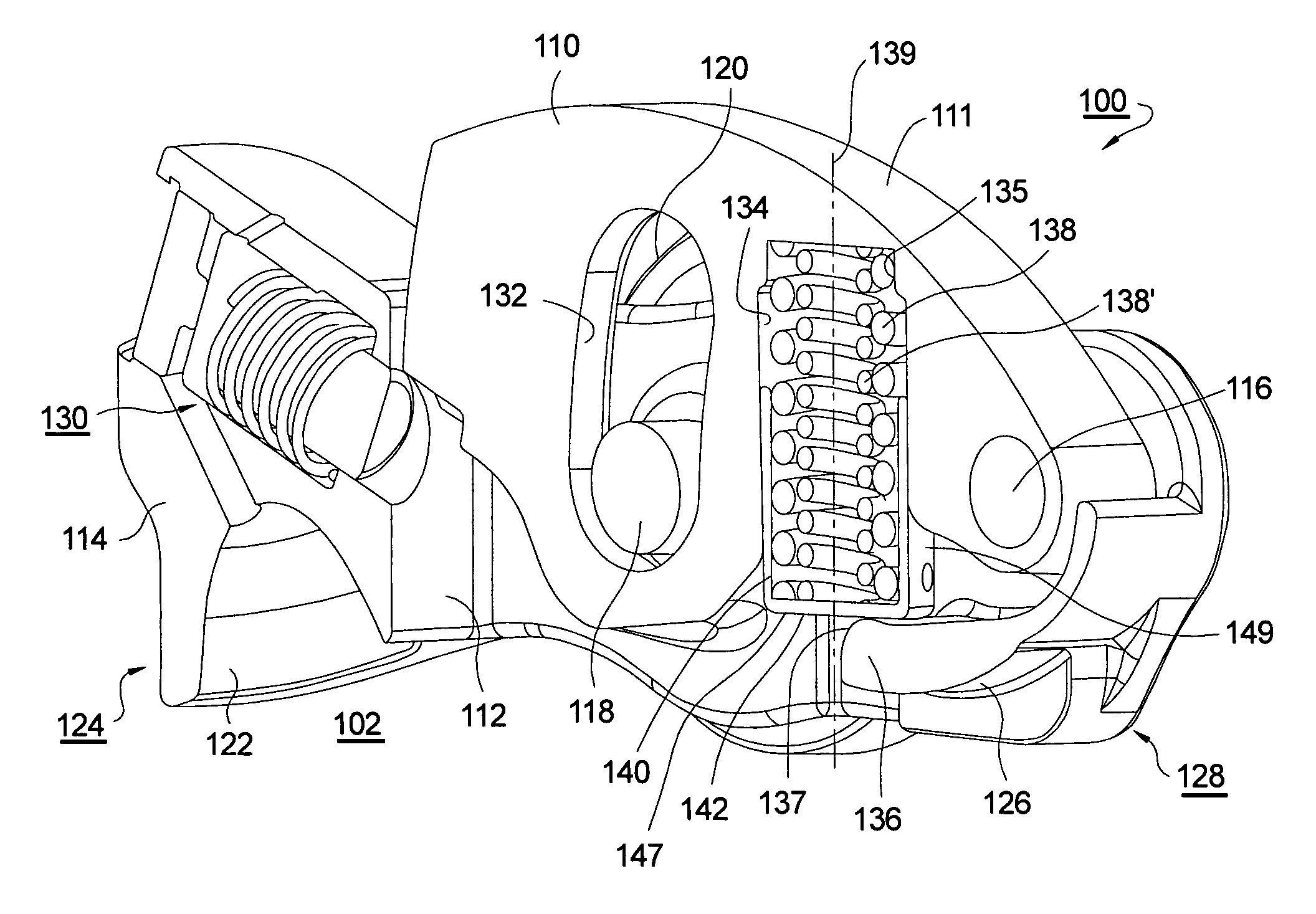
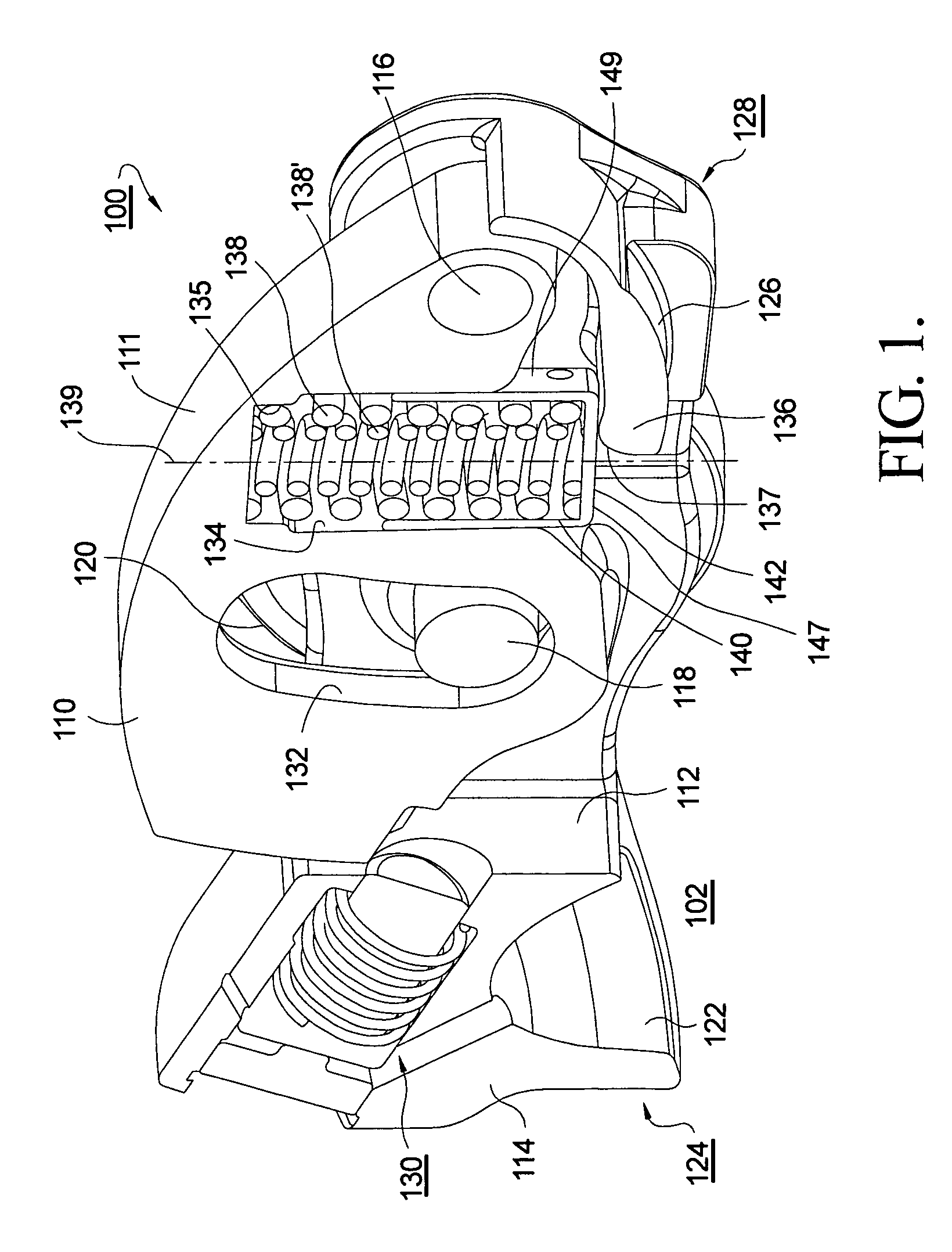
[0019]Referring to FIG. 1, a first embodiment 100 of a two-step roller finger follower in accordance with the invention is formed generally in accordance with the two-step RFF prior art. Such a two-step RFF is suitable for use in a variable valve activation system of an internal combustion engine 102. The view shown in FIG. 1 represents a section cutaway along a vertical symmetry plane for description purposes such that only one-half of the RFF is present. Thus, where appropriate, the described elements should be considered as having matching but not shown counterparts in the full RFF.

[0020]A high-lift follower 110 including a cam-follower surface 111 is disposed in a central opening 112 in a generally box-shaped low-lift follower 114. High-lift follower 110 pivots within opening 112 about a pivot shaft 116. A roller shaft 118 mounted in low-lift follower 114 supports a roller 120 for following a low-lift lobe of an engine camshaft (not shown). Low-lift follower 114 includes a socke...


PUM


Abstract

A two-step roller finger follower having a high-lift follower portion that rotates relative to a low-lift follower portion about a pivot shaft, including a lost-motion compression spring disposed in a linear bore formed in the high-lift portion to exert force against an curved pad on the back side of the valve pallet of the low-lift portion. The spring is retained and guided in its bore by a spring retainer having a planar bottom for engaging the curved pad. Preferably the retainer is a cup positioned in the spring bore such that the stroke of the cup is limited, to prevent leak-down of the associated hydraulic lash adjuster. Driving the spring by a linear-acting retainer in a linear bore causes the spring to be compressed linearly, resulting in a highly stable and predictable spring rate.

Description

TECHNICAL FIELD[0001]The present invention relates to roller finger followers for actuating the valves of internal combustion engines; more particularly, to two-step roller finger followers for controllably activating and deactivating engine valves; and most particularly, to a two-step roller finger follower having a guided lost-motion compression spring.BACKGROUND OF THE INVENTION[0002]Two-step roller finger followers (RFF) for controllably activating compression valves in a variable valve actuation train in an internal combustion engines are well known. An RFF extends between a hydraulic lash adjuster (HLA) and the stem of a valve. Engagement with a cam lobe of an engine camshaft causes the RFF to be pivoted about the HLA and thereby to depress the valve stem, opening the valve. A two-step RFF mechanism allows an engine valve to be operated by two different cam lobe profiles, one with the mechanism locked and the other with the mechanism unlocked. When the mechanism is unlocked, t...

Claims


Application Information

Patent Timeline
Patent Type & Authority Patents(United States)
IPC IPC(8): F01L1/18
CPCF01L1/185F01L13/0036Y10T74/2107Y10T74/20882F01L2001/186F01L2001/467
Inventor FERNANDEZ, HERMES A.LIPINSKI, ANDREW J.HENDRIKSMA, NICK J.FISCHER, THOMAS H.KUNZ, TIMOTHY W.
Owner DELPHI TECH IP LTD
Why Eureka
Try Eureka