Impact hammer drill

a hammer drill and impact technology, applied in the field of drilling machines, can solve the problems of inability to adjust the intensity of the impact generated, the lowering of the motive energy of the drill bit rotation, and the inability to use the drilling machine at places subject to noise regulation, etc., and achieves low noise, high speed, and the effect of low nois

Inactive Publication Date: 2007-12-11
KOKI HLDG CO LTD
View PDF36 Cites 27 Cited by
  • Summary
  • Abstract
  • Description
  • Claims
  • Application Information

AI Technical Summary

Benefits of technology

[0007]It is therefore an object of the present invention to overcome the above-mentioned drawbacks, and to provide a drilling machine capable of performing drilling operation at a high speed with low noise and without requiring a large thrust.

Problems solved by technology

However, a drilling machine employing impacts cannot be used at places subject to noise regulation due to noise brought about when applying impacts.
However, when using a conventional drilling machine employing impacts, since part of motive energy to rotate a drill bit is used as motive energy to generate impacts, motive energy to rotate a drill bit is lowered, and intensity of thus generated impacts cannot be adjusted.
There is raised a problem that, when drilling concrete, the drilling speed of a drilling machine that employs only rotational motion and is not provided with an impact mechanism to apply impacts to a drill bit is extremely lowered when running into a high hardness aggregate such as a coarse aggregate.
On the other hand, in case the drilling operation is performed in an upward direction, a drilling machine has to be uplifted and a load as a thrust has to be applied to the drill bit, which requires a hard labor.
Furthermore, as for noise countermeasures, since a drilling machine has to be selected from only two drilling machines, that is, a drilling machine employing impacts with high noise and a drilling machine employing only rotational motion with low noise, there may be raised a case in which the drilling machine employing impacts cannot clear noise regulation while noise of the drilling machine employing only rotational motion is extremely low as compared with noise set down by noise regulation.
In this case, the drilling machine employing only rotational motion alone can be used, which undesirably lowers working efficiency.

Method used


Image

  • Impact hammer drill
  • Impact hammer drill
  • Impact hammer drill

Examples


Embodiment Construction

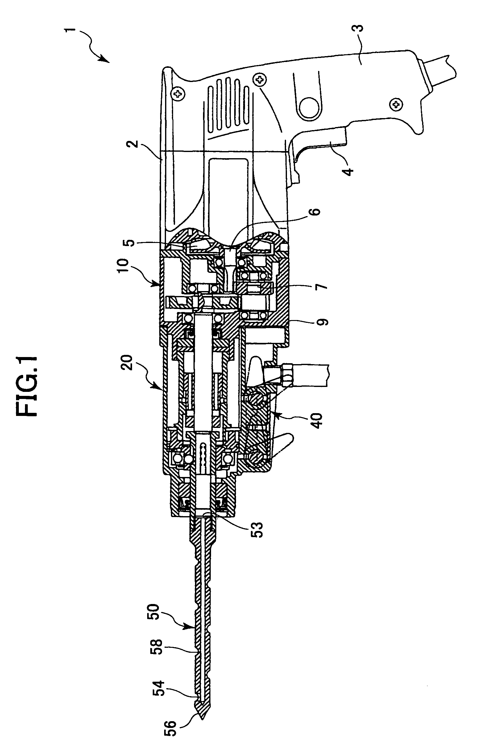
[0019]A drilling machine according to an embodiment of the present invention will be described with reference to FIG. 1 to FIG. 9. In the present embodiment, compressed air is used as a compressed fluid. One end of a drilling machine 1, having a drill bit 50 to be described later, is set to be the front side, while the other end thereof is set to be the rear side.

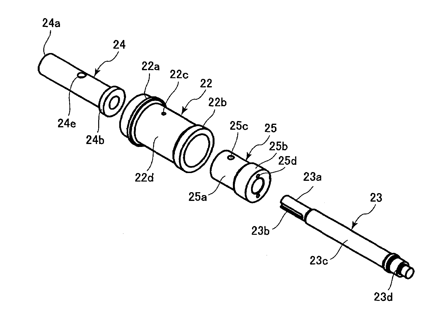
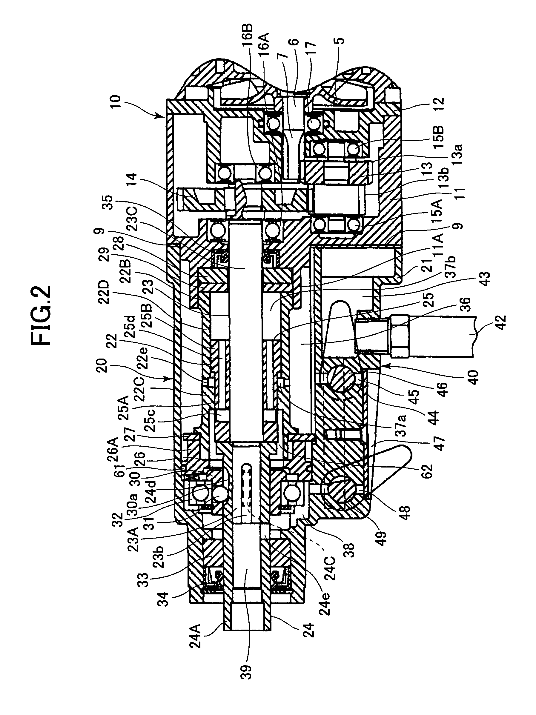
[0020]The drilling machine 1 shown in FIG. 1 includes a housing 2 as a main frame of the drilling machine 1, a deceleration unit 10, a cylinder unit 20, a compressed air supplying unit 40, and a drill bit 50. The deceleration unit 10 is disposed at the front part of the housing 2. The cylinder unit 20 accommodating therein a piston drive unit is disposed at the front side of the deceleration unit 10. The compressed air supplying unit 40 is disposed at the front side of the housing 2 and below the cylinder unit 20. The drill bit 50 is disposed at the front side of the cylinder unit 20.

[0021]The housing 2, which configures a ...


PUM

PropertyMeasurementUnit
flow rateaaaaaaaaaa
cylindrical shapeaaaaaaaaaa
inner diameteraaaaaaaaaa

Abstract

An impact hammer drill capable of performing drilling operation at a high speed with low noise and without requiring a large thrust. The drill includes a main shaft rotatable by an output shaft of a motor, and a spindle having an impact-receiving section and disposed over the main shaft slidably in its axial direction and rotatable together with the rotation of the main shaft. A piston is reciprocatingly slidably disposed over the main shaft for impacting against the impact-receiving section. A piston drive unit is disposed for driving the piston with a compressed fluid. A compressed fluid supplying unit is disposed for supplying the compressed fluid to the piston drive unit. A drill bit is attachable to the spindle. When performing drilling operation, the drill bit is imparted with a combined rotational motion and the reciprocal impact motion.

Description

BACKGROUND OF THE INVENTION[0001]The present invention relates to a drilling machine, and more particularly, to a drilling machine that applies impacts on a target with a compressed air as a power source.[0002]Conventionally, when drilling a concrete or the like, applying vibrational impacts, in addition to rotational motion, to a drill bit to crush a point of the concrete is known as the fastest drilling method. So as to apply such impacts to a drill bit, generally, part of rotational motion of a motor or the like that rotates a drill bit of a drilling machine is converted to reciprocating motion of a piston etc. arranged in the drilling machine. Then, impacts to be applied to the drill bit are generated from such reciprocating motion of the piston.[0003]However, a drilling machine employing impacts cannot be used at places subject to noise regulation due to noise brought about when applying impacts. As a conventional drilling machine that is intended to be used at places subject t...

Claims


Application Information

Patent Timeline
Patent Type & Authority Patents(United States)
IPC IPC(8): B25B19/00B25D9/04B23B45/16B25D16/00B25D17/22B28D1/26
CPCB25D9/04B25D16/00B25D17/22B25D2250/195B25D2216/0038B25D2250/095B25D2216/0023
Inventor ODA, HIROYUKITERUNUMA, YUKIOOGURA, MASAYUKI
Owner KOKI HLDG CO LTD
Why Eureka
Try Eureka