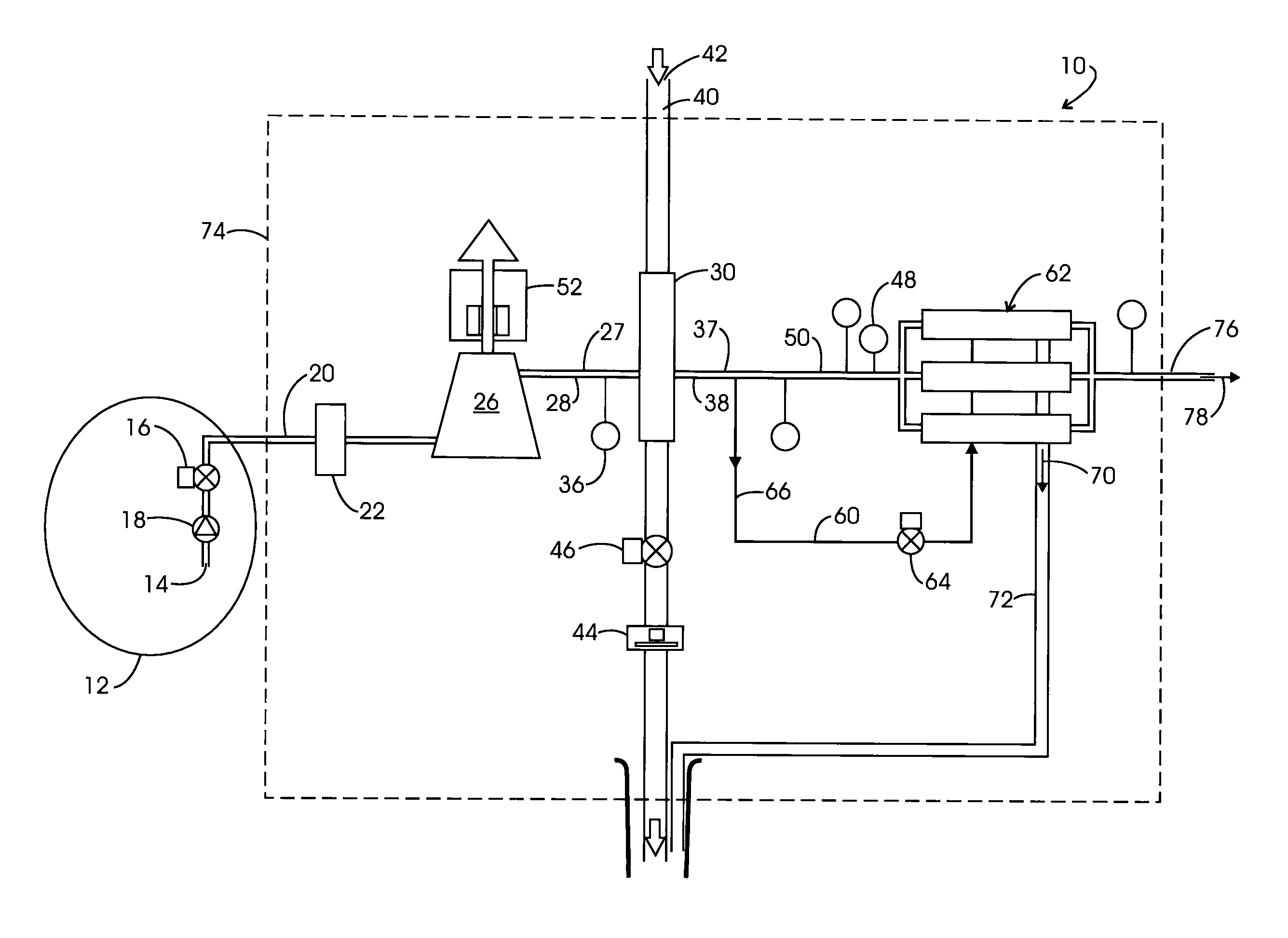
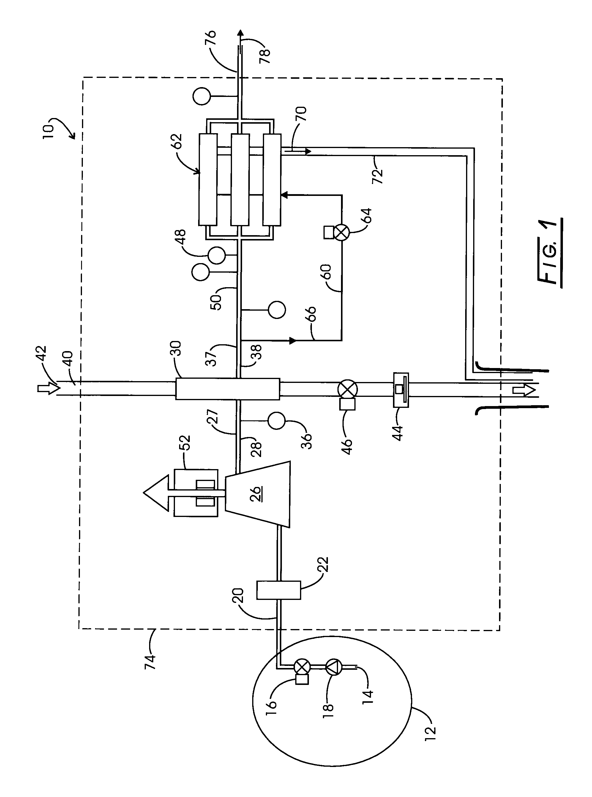
[0016]In another embodiment of the invention, an aircraft, in an on-board inert gas generating system, includes: a. a source of aircraft cabin air; b. a motor-driven radial flow centrifugal compressor, having an input side connected with the source of cabin air, for compressing the cabin air and thereby raising the temperature thereof to a first temperature range, the compressor concomitantly producing a first variable airflow portion while also producing a second, excess, airflow portion in order to keep the compressor from surging in certain predetermined operating modes; c. a heat exchanger, having an upstream side thereof connected with an output side of the compressor, for reducing the temperature of the compressed air first airflow portion to a second temperature range; and d. an air separator module of the permeable membrane type, utilizing multiple, parallel, membrane bundles encased in an outer shell portion, having an input port operatively interconnected with a downstream side of the heat exchanger, for receiving and separating the airflow first portion of the second temperature compressed air into nitrogen enriched air and oxygen enriched air, wherein the improvement comprises: e. the addition of a conduit, connecting an upstream side of the heat exchanger with the inlet side of a turbofan turbine, for directing the second, excess, airflow portion of the first temperature compressed air to the turbine for driving the turbofan for heat exchanger cooling purposes, thereby utilizing at least some of the energy of the second, excess, airflow portion first temperature compressed air. A variation of this embodiment further includes a surge valve, operatively interposed in the conduit, for controlling the flow of the second, excess airflow portion of the first temperature compressed air to the turbofan turbine. A further variation of this embodiment includes the addition of a further conduit, connecting the outlet of the turbofan turbine with the air separator module outer shell portion, for further directing the second, excess, airflow portion of the first temperature compressed air over and around the multiple membrane bundles, thereby utilizing additional energy of the second, excess, airflow portion first temperature compressed air for performing at least one of warming up and maintaining a predetermined temperature operating range within the separator module, before exiting from the shell portion.
[0017]In yet a further embodiment of this invention, an aircraft, in an on-board inert gas generating system, includes: a. a source of aircraft cabin air; b. a motor-driven radial flow centrifugal compressor, having an input side connected with the source of cabin air, for compressing the cabin air and thereby raising the temperature thereof to a first temperature range, the compressor concomitantly producing a first variable airflow portion while also producing a second, excess, airflow portion in order to keep the compressor from surging during certain predetermined operating modes; c. a heat exchanger, having an upstream side thereof connected with an output side of the compressor, for reducing the temperature of the compressed air first airflow portion to a second temperature range; and d. an air separator module of the permeable membrane type, utilizing multiple, parallel membrane bundles encased within an outer shell portion, having an input port operatively interconnected with a downstream side of the heat exchanger, for receiving and separating the airflow first portion of the second range compressed air into nitrogen enriched air and oxygen enriched air, wherein the improvement comprises: e. the addition of a first conduit, connecting an upstream side of the heat exchanger with the inlet side of a turbofan turbine, for directing the second, excess, airflow portion of the first temperature compressed air to the turbine for driving the turbofan for heat exchanger cooling purposes, thereby utilizing at least some of the energy of the second, excess, airflow portion first temperature compressed air; and f. the addition of a second conduit, connecting the outlet of the turbofan turbine with the air separator module outer shell portion, for further directing the second, excess, airflow portion of the first temperature compressed air over and around the multiple membrane bundles, thereby utilizing additional energy of the second, excess, airflow portion first temperature compressed air for performing at least one of warming up and maintaining a predetermined temperature operating range within the air separator module, before exiting from the shell portion. A variation of this embodiment further includes a surge valve, operatively interposed in the first conduit, for controlling the flow of the second, excess airflow portion of the first temperature compressed air to the turbofan turbine.
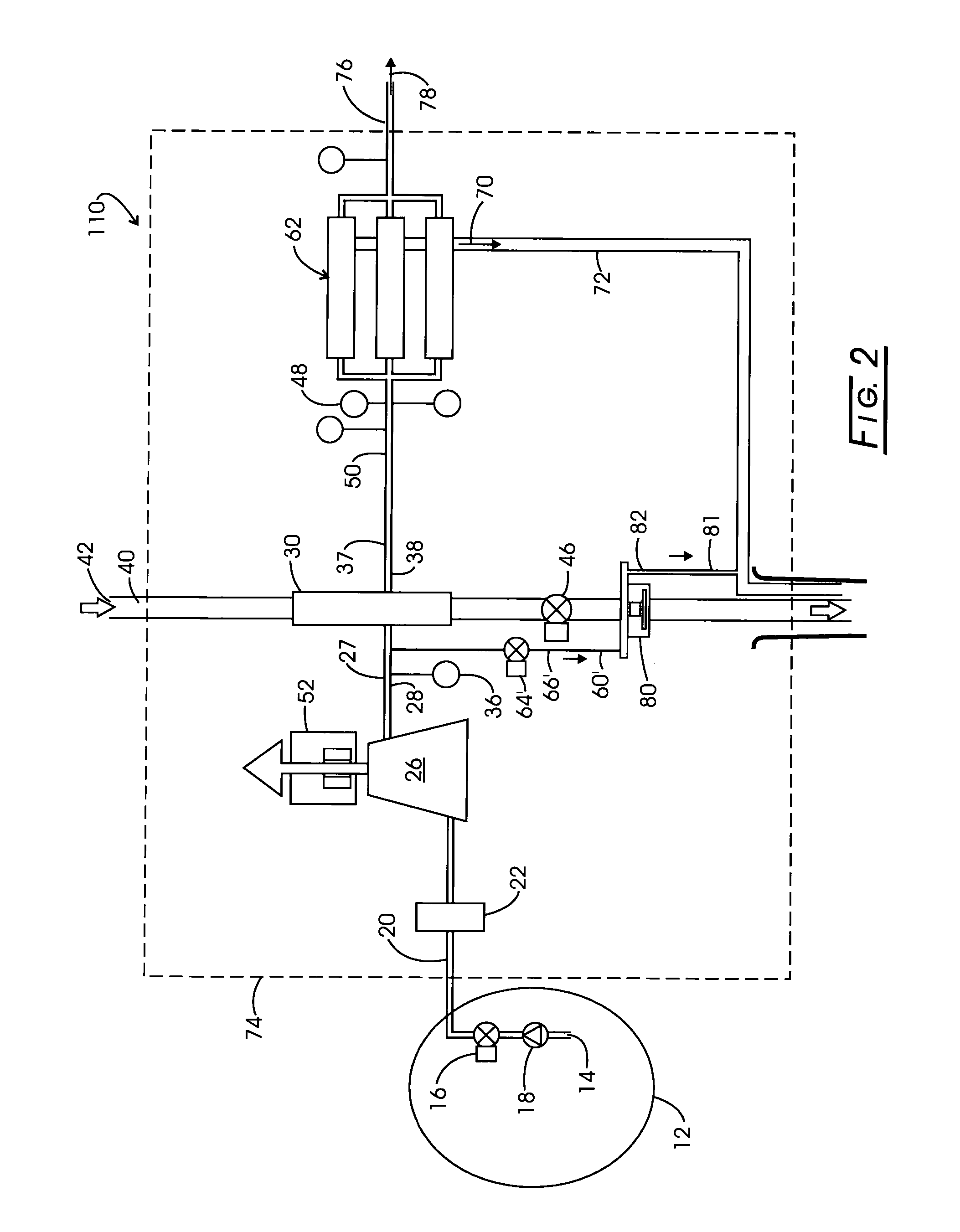
[0019]In still another embodiment of this invention, in an aircraft, an on-board inert gas generating system, includes: a. a source of aircraft cabin air; and b. a motor-driven radial flow centrifugal compressor, having an input side connected with the source of cabin air, for compressing the cabin air and thereby raising the temperature thereof to a first predetermined temperature range, the compressor producing a first variable airflow portion while concurrently producing a second, excess, airflow portion in order to keep the compressor from surging in certain predetermined operating ranges, wherein the improvement comprises: c. the addition of a conduit, connecting an output side of the compressor with the inlet side of a turbofan turbine, for directing the second, excess, airflow portion of the compressed air to the turbine for driving the turbofan for heat exchanger cooling purposes, thereby utilizing at least some of the energy of the second, excess, airflow portion. In a variation of this embodiment, the system further includes: d. a heat exchanger, having an upstream side thereof also connected with the output side of said compressor, for reducing the temperature of said compressed air first airflow portion to a second temperature range; and e. an air separator module of the permeable membrane type, utilizing multiple, parallel membrane bundles encased within an outer shell portion, having an input port operatively interconnected with a downstream side of the heat exchanger, for receiving and separating the airflow first portion of the second range compressed air into nitrogen enriched air and oxygen enriched air, wherein the improvement further comprises: f. the addition of a further conduit, connecting the outlet side of the turbofan turbine with the air separator module outer shell portion, for further directing the second, excess, airflow portion of the first temperature compressed air over and around the multiple membrane bundles, thereby utilizing additional energy of the second, excess, airflow portion first temperature compressed air for performing at least one of warming up and maintaining a predetermined temperature operating range within the air separator module, before exiting from the shell portion. A first variation of this embodiment further includes a surge valve, operatively interposed in at least one of the conduits, for controlling the flow of the second excess, airflow portion of the first temperature compressed air.

