System and method for determining light source current

a light source current and system technology, applied in the field of scanning technology, can solve the problems of affecting the digital reproduction of scanned documents, preventing the faithful reproduction of hardcopy documents into digital form, and affecting the accuracy of scanning documents

Active Publication Date: 2007-12-11
HEWLETT PACKARD DEV CO LP
View PDF22 Cites 41 Cited by
  • Summary
  • Abstract
  • Description
  • Claims
  • Application Information

AI Technical Summary

Benefits of technology

[0009]The application of predefined currents to the LED's employed in a scanner helps make light output for each LED more uniform.

Problems solved by technology

With all the promise and benefits of scanning technology, it still is plagued with various problems that may often prevent the faithful reproduction of hardcopy documents into digital form.
For example, many scanners include inherent imperfections that mar the digital reproduction of scanned documents.
In addition, typically scanners are plagued with sensor failure over time due to degradation, usage, and incidental damage, etc.
For example, in some cases, over time a few sensors may experience failure and constantly emit a single output voltage due to damage or degradation.
Such failure may manifest itself in the appearance of vertical streaks or lines in a digital document produced by such a scanner.
Unfortunately, it is difficult to counter the effects of such errant sensors.

Method used


Image

  • System and method for determining light source current
  • System and method for determining light source current
  • System and method for determining light source current

Examples


Embodiment Construction

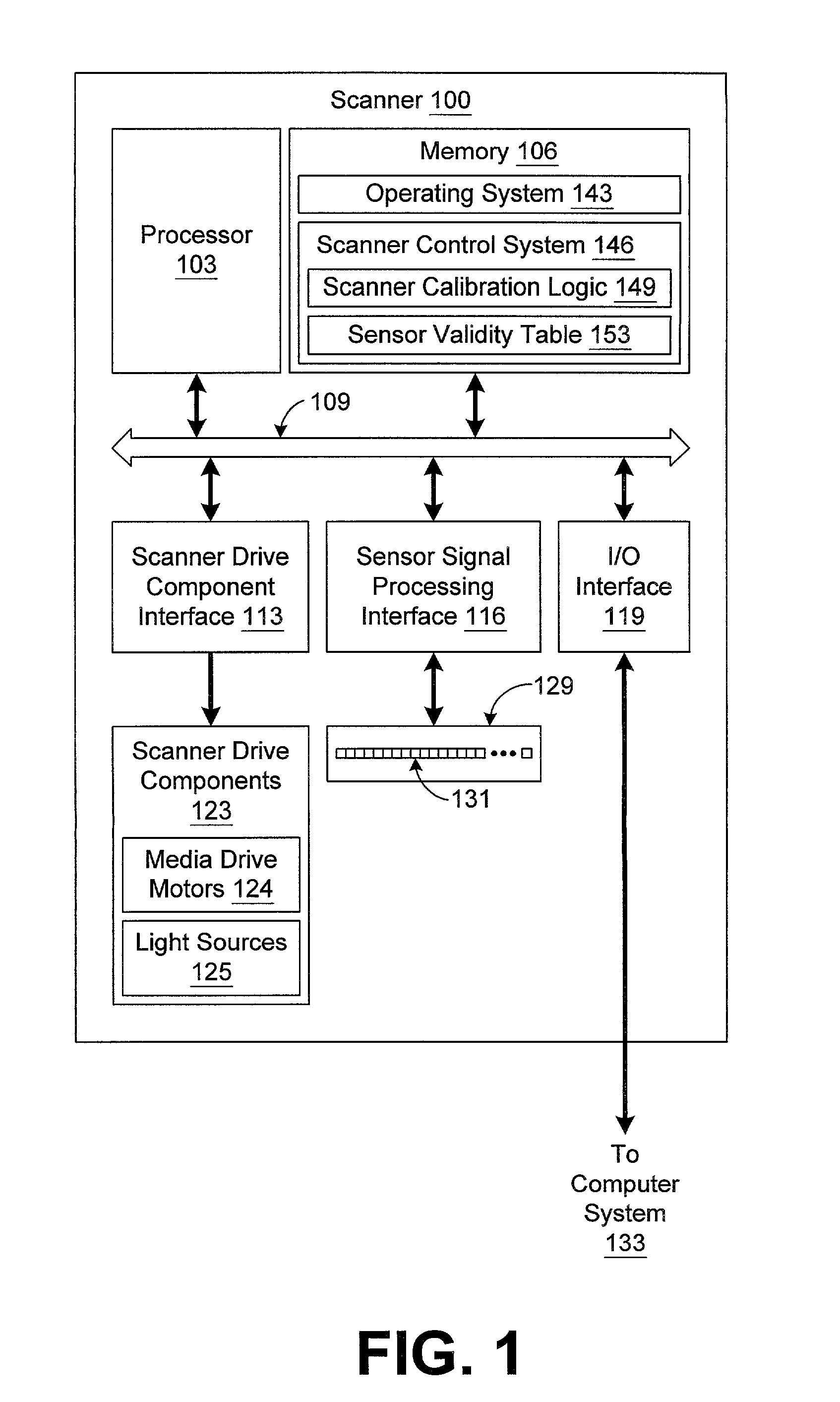
[0020]Turning to FIG. 1, shown is a scanner 100 according to an aspect of the present invention. The scanner 100 includes a processor circuit with a processor 103 and a memory 106, both of which are coupled to a local interface 109. The local interface 109 may be, for example, a data bus with an accompanying control bus as is generally known by those with ordinary skill in the art. Coupled to the local interface 109 is a scanner drive component interface 113, a sensor signal processing interface 116, and an input / output (I / O) interface 119. The scanner 100 also includes scanner drive components 123 that are coupled to the local interface 109 through the scanner drive component interface 113.

[0021]The scanner drive components 123 may include, for example, media drive motors 124, scanner light sources 125, indicator lights, and other components that are employed in the general operation of a scanner 100 as is generally known by those with ordinary skill in the art. The drive motors 12...


PUM


Abstract

A system and method are provided for determining a light output of a light emitting diode (LED) in a scanner. The system includes a processor circuit to execute current control logic to obtain an optimum light output from the LED. The current control logic repeatedly applies increasing or decreasing currents to the LED until a saturation point is identified. This may be accomplished, for example, by comparing two measures of the light output of the LED for two different currents applied to the LED. When a difference equaling a predetermined threshold between the two measures is detected, then the saturation point is identified.

Description

CROSS REFERENCE TO RELATED APPLICATIONS[0001]This application is related to co-pending U.S. patent application entitled “System and Method for Scanner Calibration” assigned Ser. No. 09 / 855,211 and filed on even date herewith.TECHNICAL FIELD[0002]The present invention is generally related to the field of scanning technology and, more particularly, is related to a system and method for scanner calibration.BACKGROUND OF THE INVENTION[0003]With the dawn of the information age, scanning technology that is employed to convert paper or other documents into digital documents plays an important role. In particular, scanning technology plays a very important role in reducing the amount of paper that is created in a typical business environment. Scanners contribute to an increase in the speed at which business affairs are conducted. For example, documents that are scanned into digital form may then be transmitted to recipients via the Internet or other network rather than using traditional mai...

Claims


Application Information

Patent Timeline
Patent Type & Authority Patents(United States)
IPC IPC(8): G01R35/00G01J1/00H04N1/00H04N1/193
CPCG01J1/00H04N1/00002H04N1/00013H04N1/00031H04N1/00063H04N1/00068H04N1/00087H04N1/0282H04N1/00053H04N1/193
Inventor JENSEN, NANETTE C.KEITHLEY, DOUGLAS G.CAPPS, VIRGINIA K.BOHAN, DAVID G.
Owner HEWLETT PACKARD DEV CO LP
Why Eureka
Try Eureka