Method for breaking a flap-valve attachment condition under a membrane cover

a technology of flap valve and attachment condition, which is applied in the direction of containers, water/sludge/sewage treatment, water/sludge/sewage treatment, etc., can solve the problems of membrane bursting, cover exposed to elements, localized elongation, etc., and achieves easy breaking of flap valve attachment condition, reducing capillary effect, and surface tension

Active Publication Date: 2007-12-18
EVOQUA WATER TECH CANADA LTD
View PDF25 Cites 4 Cited by
  • Summary
  • Abstract
  • Description
  • Claims
  • Application Information

AI Technical Summary

Benefits of technology

[0035]In the present invention there is provided a new method for breaking flap-valve attachment conditions in a membrane cover. There is also provide a method and a membrane structure to reduce the effects of flap-valve attachment conditions in a covered reservoir, and by the same action to reduce the formation of gas pockets under a membrane cover.
[0038]This method causes the width of a region of adherence between the membrane cover and the liquid surface to be reduced to zero, thereby breaking the flap-valve attachment condition and allowing the accumulation of bio-gases to flow into or to slowly migrate toward the gas passage.
[0039]In another aspect of the present invention, there is provided a method for more easily breaking flap-valve attachment conditions. This method comprises the steps of; making equal the pressure in the gas passage and the pressure under the cover in the central region of the reservoir, and providing a membrane cover that has a turbulence-inducing surface thereon in contact with the liquid surface of the reservoir. Such turbulence-inducing surface has the ability to break the surface tension in the liquid inside the reservoir, and to reduce the capillary effect between the membrane cover and the liquid surface inside the reservoir. Because of these reductions in adhesion forces between the membrane cover and the liquid surface, the flap-valve attachment conditions present under the membrane cover are more easily broken when the pressure under the cover is made equal everywhere.
[0040]In yet another aspect of the present invention, the membrane cover is provided with a stiff layer therein to prevent the membrane from flexing and following the curvatures of waves and ripples at the liquid surface under the cover. Because of this increase in stiffness, the flap-valve attachment conditions are still more easily broken when the pressure under the cover is made equal everywhere.

Problems solved by technology

The maintenance of a membrane cover floating on a large wastewater reservoir represents certain difficulties in that the cover is exposed to the elements, and especially to wind uplift and wind-induced fluttering.
These movements and stresses can cause fatigue, localized elongation and can eventually rupture the membrane.
Such walking activities on a membrane cover wears the membrane material and reduces the life of the cover.

Method used


Image

  • Method for breaking a flap-valve attachment condition under a membrane cover
  • Method for breaking a flap-valve attachment condition under a membrane cover
  • Method for breaking a flap-valve attachment condition under a membrane cover

Examples


Embodiment Construction

[0050]While this invention is susceptible of embodiments in many different forms, there is shown in the drawings and will be described in details herein one specific embodiment of a method for breaking a flap-valve attachment phenomenon, with the understanding that the present disclosure is to be considered as an example of the principles of the invention and is not intended to limit the invention to the embodiment illustrated and described.

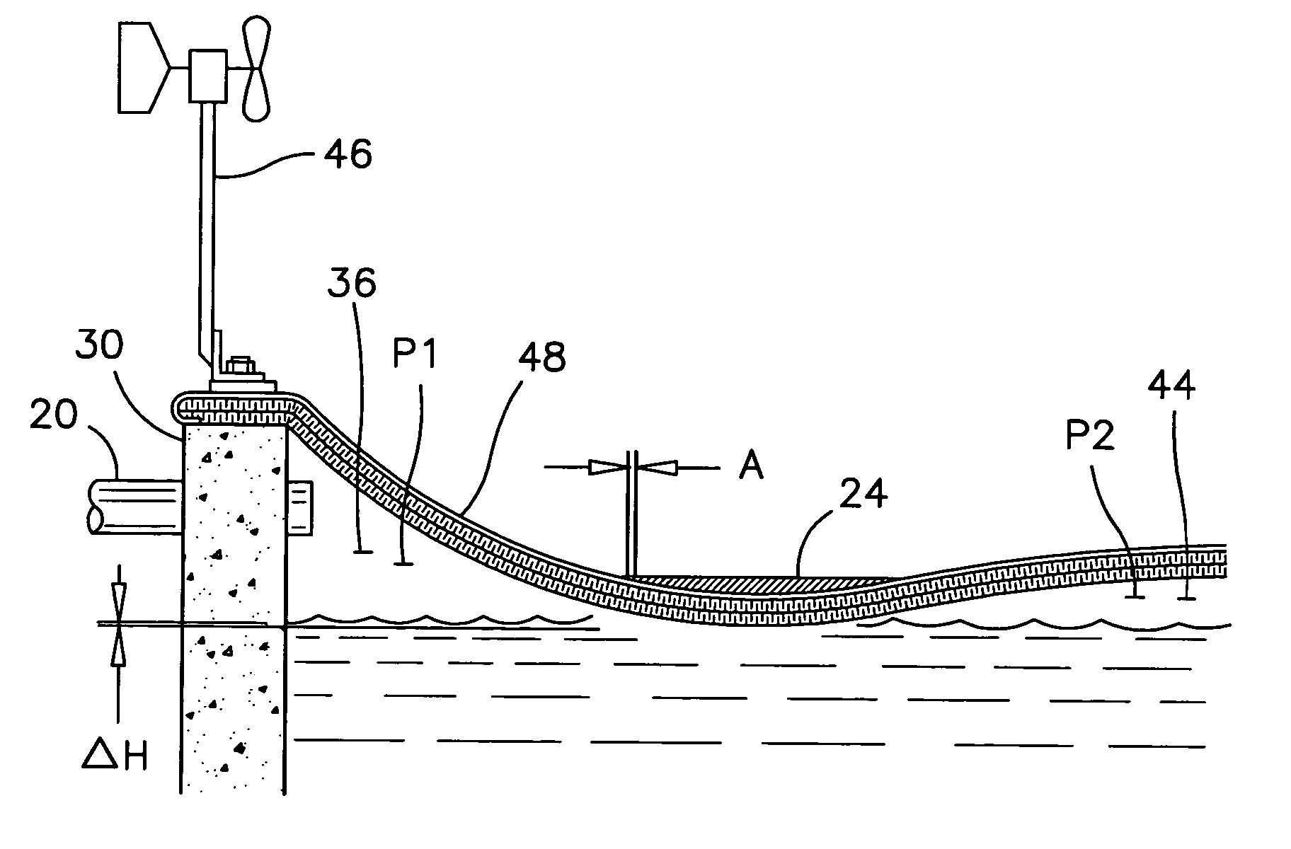
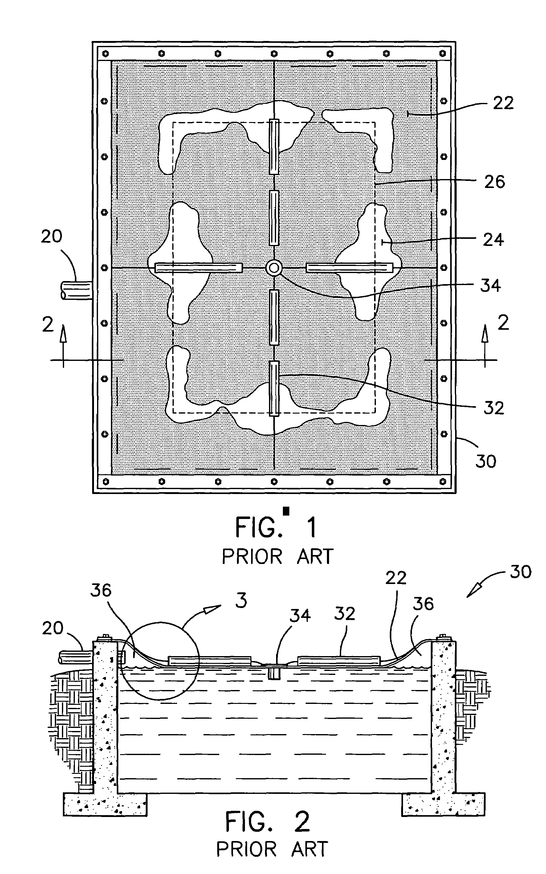
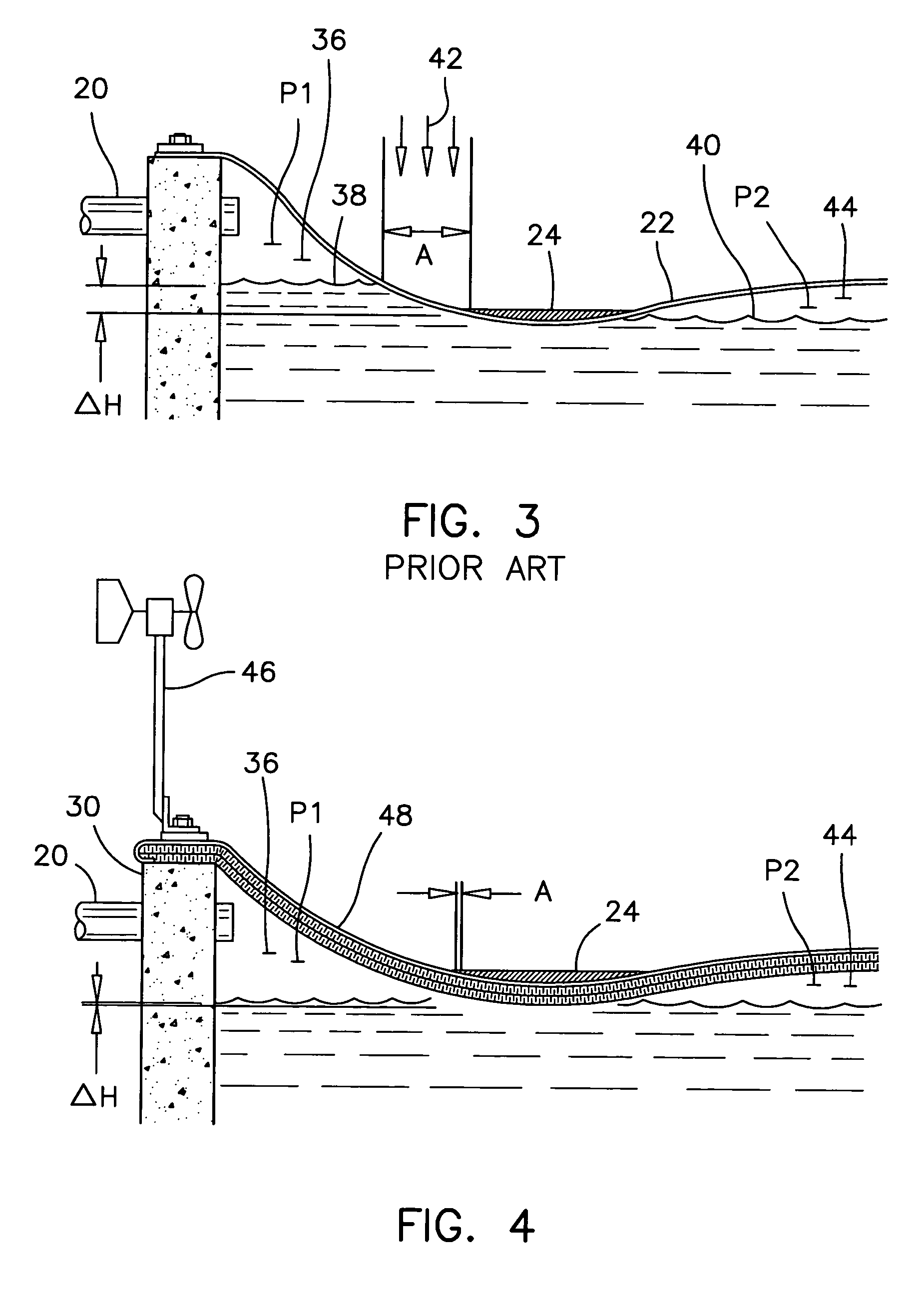
[0051]There are two facets to the method according to the preferred embodiment of the present invention. A first step in this method consists of equalizing the pressure under the membrane cover, and the other step consists of providing a stiff and rough-surfaced membrane. It has been found that a stiff and rough-surfaced membrane reduces the capillary effect between the membrane surface and the liquid surface inside the reservoir, and therefore facilitate the breaking of a flap-valve attachment condition.

[0052]While the first step is sufficient t...


PUM

PropertyMeasurementUnit
widthaaaaaaaaaa
pressureaaaaaaaaaa
speedaaaaaaaaaa

Abstract

In a covered wastewater reservoir, a gas passage is defined under the membrane cover and along the sides of the reservoir. An accumulation of bio-gases is held captive between the membrane cover and the liquid surface in a central region of the reservoir relative to the gas passage, by a flap-valve attachment condition extending between the accumulation of bio-gases and the gas passage. The new method for breaking this flap-valve attachment condition and for allowing bio-gases to flow from the accumulation of bio-gases toward the gas passage, consists of periodically and momentarily increasing a pressure in the gas passage to equal or to slightly exceed a pressure in the accumulation of bio-gases. In another aspect, the membrane cover is provided with a stiff and rough-surfaced bottom layer to facilitate the breaking of flap-valve attachment conditions when the pressure under the cover is made equal everywhere.

Description

FIELD OF THE INVENTION[0001]This invention pertains to the maintenance of floating membrane covers on large industrial, municipal and agricultural reservoirs, and more particularly it pertains to a method to reduce the formation of gas pockets under a floating membrane cover.BACKGROUND OF THE INVENTION[0002]Floating membrane covers are mounted over settling ponds and clarifiers to contain and collect fermentation gases of mill effluents for example, and in many cases, to prevent the accumulation of rainwater inside these reservoirs. The maintenance of a membrane cover floating on a large wastewater reservoir represents certain difficulties in that the cover is exposed to the elements, and especially to wind uplift and wind-induced fluttering.[0003]The fermentation of wastewater in a covered reservoir generates bio-gases that tend to create gas pockets under the cover. Following a rainfall, rainwater accumulates around the gas bubbles, thereby creating puddles, mounds and relaxed seg...

Claims


Application Information

Patent Timeline
Patent Type & Authority Patents(United States)
IPC IPC(8): B65D88/34C02F3/28B01D21/30B65D88/36B65D90/00B65D90/32C02F1/00C02F3/00E04H15/20E04H15/54
CPCA01C3/028Y02E50/343Y02E50/30
Inventor DEGARIE, CLAUDE J.
Owner EVOQUA WATER TECH CANADA LTD
Why Eureka
Try Eureka