Electronic apparatus, electronic system, and driving method for electronic apparatus

a technology of electronic equipment and electronic system, applied in the direction of instruments, static indicating devices, electroluminescent light sources, etc., can solve the problems of insufficient low-grayscale data signal writing, above-described problem becomes noticeable, and takes time to write low-grayscale data signals, etc., to achieve the effect of increasing cost and precise brightness

Inactive Publication Date: 2007-12-18
ELEMENT CAPITAL COMMERCIAL CO PTE LTD
View PDF33 Cites 230 Cited by
  • Summary
  • Abstract
  • Description
  • Claims
  • Application Information

AI Technical Summary

Benefits of technology

[0010]In order to address or solve the above and / or other problems, the present invention provides an electronic apparatus, an electronic system, and a driving method for an electronic apparatus in which images can be displayed with a precise level of brightness even in a low-grayscale display area without increasing the cost.
[0023]A pair of unit circuits may be connected to one data line, and one of a pair of control lines to control the output of each of the electronic devices may be connected to the corresponding unit circuit, and the other control line may be connected to the other unit circuit. Control signals having inverted phase portions, which are close or adjacent to each other, may be supplied to the corresponding control lines. According to the control signals having inverted phase portions, which are close to or adjacent to each other, electronic devices disposed adjacent to each other in the direction of the data line can be driven in inverted phases in a short period of time in which a time difference can be visually negligible, thereby making it possible to compensate for the intermittency of pulse driving.
[0025]A pair of control lines may be crossed for the corresponding adjacent unit circuits. With this arrangement, electronic devices disposed adjacent to each other in the direction of the control line can be driven in inverted phases in a short period of time in which a time difference can be visually negligible, thereby making it possible to compensate for the intermittency of pulse driving, for example.

Problems solved by technology

In the display apparatus, however, it takes time to write low-grayscale data signals, and the writing of the low-grayscale data signals may become insufficient.
In particular, the above-described problem becomes noticeable in a method of supplying a data signal having a current level associated with the grayscale.
With a small value of current, it takes time to charge and discharge the parasitic capacitance of a data line, thereby prolonging the time required to program a predetermined value of current in a pixel circuit.
It is thus difficult to complete the data writing during a predetermined writing period (in general, during one horizontal scanning period).
As a result, as the light-emission efficiency of EL devices is increased, the program current becomes even smaller, which makes it difficult to program a precise value of current in a pixel circuit.
Accordingly, the number of data lines to connect a pixel matrix substrate and an external driver controller is increased, which makes it difficult to connect the driver controller with the pixel matrix substrate due to a decreased pitch of the data lines.
This increases the manufacturing cost of the display apparatus.

Method used


Image

  • Electronic apparatus, electronic system, and driving method for electronic apparatus
  • Electronic apparatus, electronic system, and driving method for electronic apparatus
  • Electronic apparatus, electronic system, and driving method for electronic apparatus

Examples


first exemplary embodiment

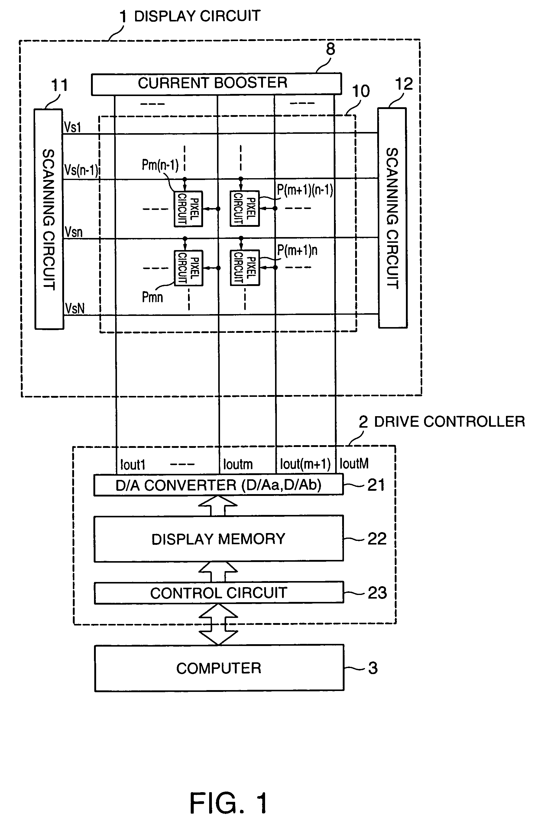
[0057]An exemplary embodiment of the present invention relates to an electro-optical apparatus provided with a drive circuit using EL devices as electro-optical devices. FIG. 1 is a schematic illustrating the overall electronic system including the electro-optical apparatus.

[0058]As shown in FIG. 1, the electronic system has a function of displaying predetermined images by using a computer, and includes at least a display circuit 1, a drive controller 2, and a computer 3.

[0059]The computer 3 is a general-purpose or dedicated computer, which outputs data (grayscale display data) to cause each pixel (dot) to display a grayscale represented by a halftone to the drive controller 2. For a color image, a halftone provided for a dot that displays each primary color is designated by grayscale display data, and a specific color pixel is generated by synthesizing the designated halftones for the primary colors.

[0060]The drive controller 2 is formed on, for example, a silicon single crystal su...

second exemplary embodiment

[0081]As described above, the second exemplary embodiment of the present invention is provided with a mode which is further developed from the electronic apparatus and the electronic system of the first exemplary embodiment.

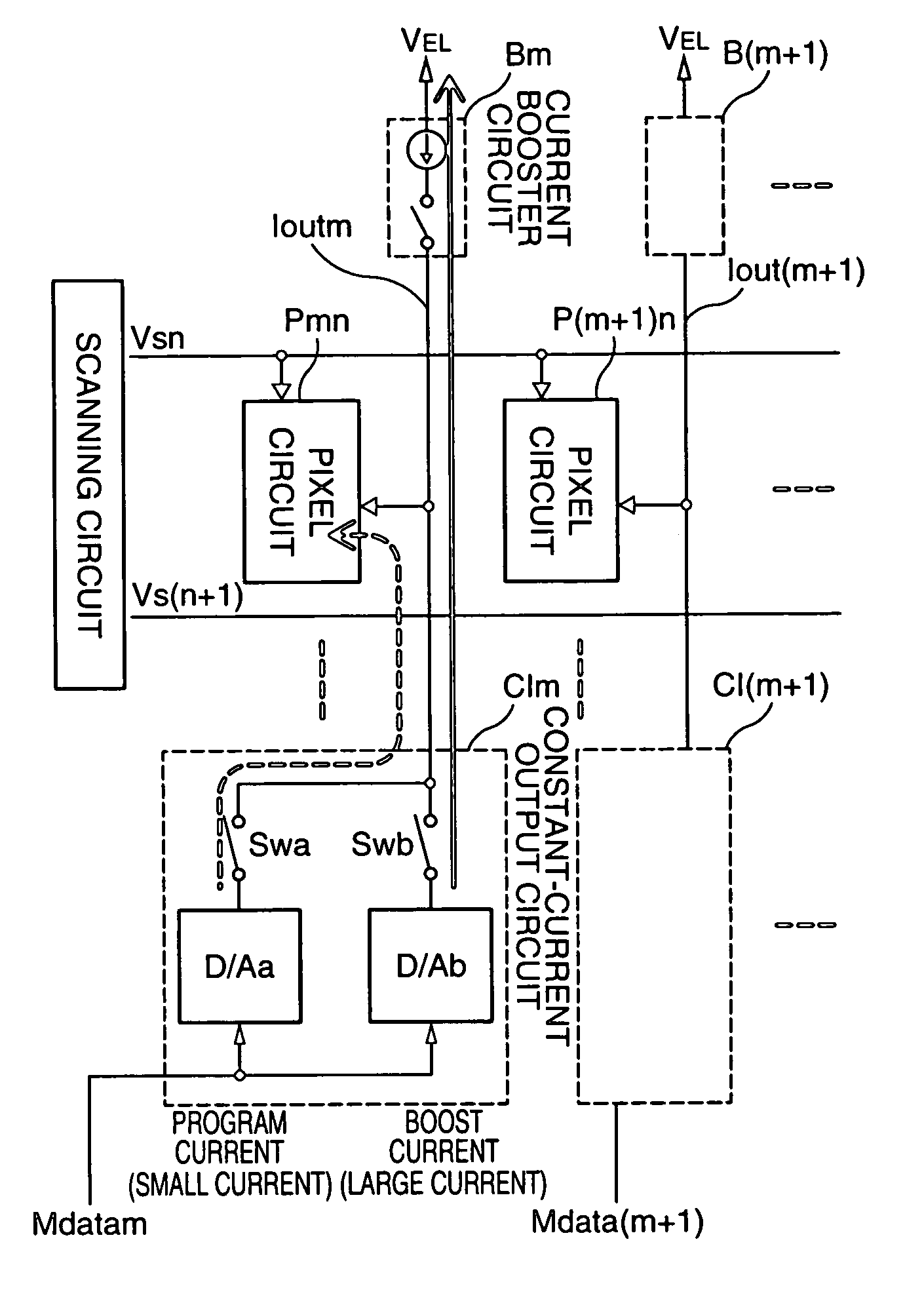
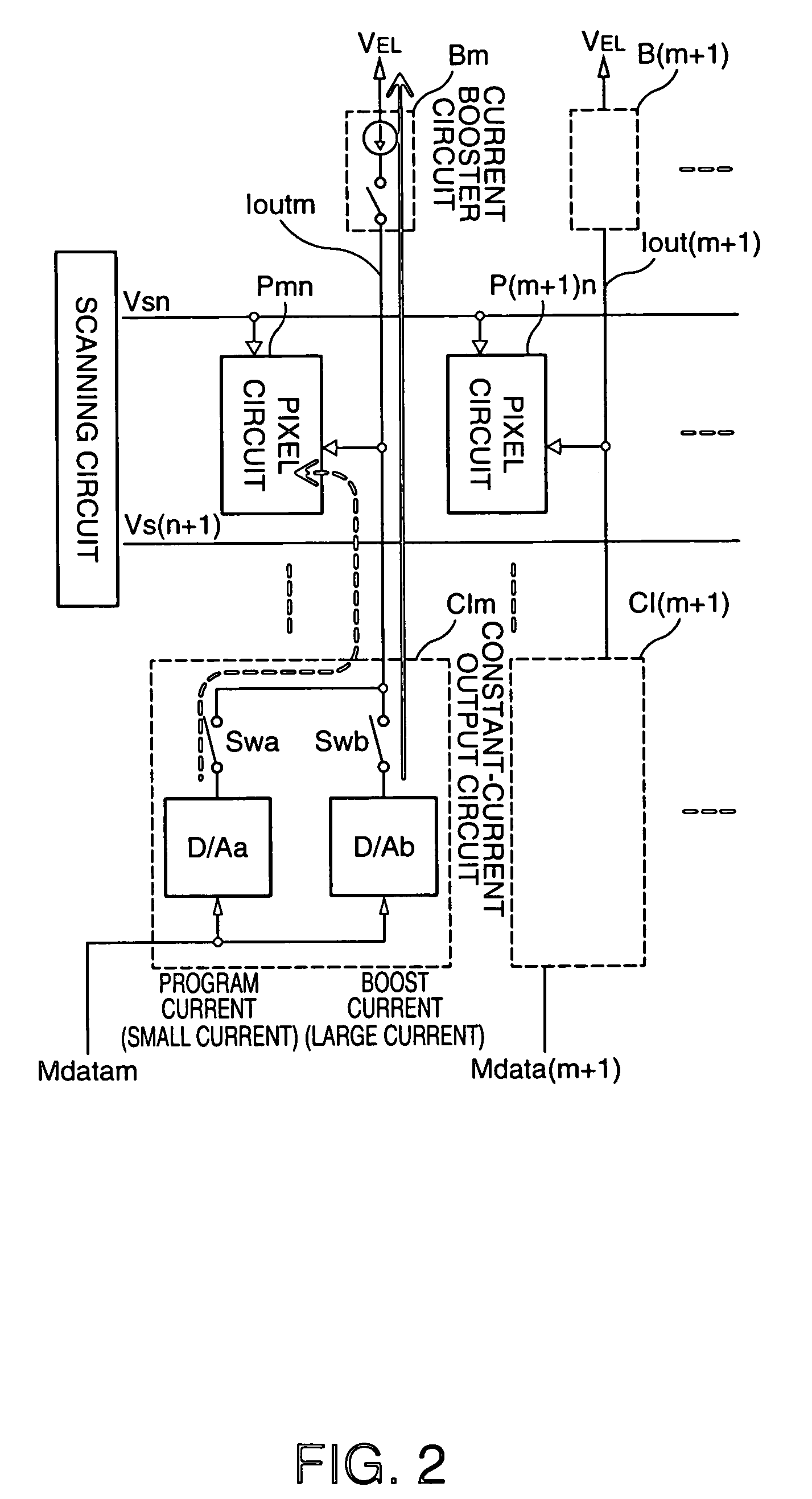
[0082]FIG. 5 illustrates the configuration of a specific electronic apparatus of the second exemplary embodiment, and FIG. 8 is a timing chart of the operation of the electronic apparatus. FIG. 5 illustrates a color pixel PmnC to perform color displaying, a current latch circuit Lm to supply a current to the color pixel, a D / A converter CIm, and a current booster circuit Bm. The blocks, such as the pixel circuit, the current booster circuit, and the constant-current output circuit (D / A converter) CIm (indicated by broken lines), are similar to those of the first exemplary embodiment, and thus, a simple explanation thereof is given. FIG. 7 illustrates an example of the circuit diagram of the current latch circuit Lm.

[0083]The configuration of the second exemplary ...

third exemplary embodiment

[0096]A third exemplary embodiment is provided with a mode that is further developed from the second exemplary embodiment so as to increase the grayscale (luminance) adjusting range, which is an object of the present invention. In particular, in the third exemplary embodiment, considering that an organic EL device is able to perform μsec-order fast switching, an organic EL device is pulse-driven by using the light-emission control line Vgn of the pixel circuit described in the first or second exemplary embodiments.

[0097]FIG. 9 is a schematic of a drive circuit of the third exemplary embodiment. FIG. 10 illustrates the principle of the third exemplary embodiment. FIG. 11 is a timing chart of the drive circuit of the third exemplary embodiment. The portions shown in FIGS. 9 and 11 that differ from those of the second exemplary embodiment are a control method for the light-emission control lines Vgn and Vg(n−1) of the pixel circuits and the connection of the light-emission control line...


PUM


Abstract

An electronic apparatus includes unit circuits provided with electronic devices, data lines connected to the unit circuits, a first output device to output, as a first output, a current or a voltage corresponding to an externally supplied data signal, a second output device to output, as a second output, a current or a voltage corresponding to the magnitude of the first output, and a selection supply device to select one of or both the first output from the first output device and the second output from the second output device and to supply the selected output to the data line. With this configuration, the image reproducibility in a low-luminance / low-grayscale display area of a display apparatus using EL devices is enhanced.

Description

BACKGROUND OF THE INVENTION[0001]1. Field of Invention[0002]The present invention relates to a drive circuit for electro-optical devices using organic electroluminescence (hereinafter “EL”). In particular, the invention relates to an enhancement in a driving method of implementing light emission with a precise level of brightness even in a low-grayscale display area.[0003]2. Description of Related Art[0004]A related art method of driving electro-optical devices, such as EL devices, includes an active-matrix driving method in which electro-optical devices can be driven with low power without causing crosstalk, and the durability of the electro-optical devices can be enhanced. Since EL devices emit light with a level of luminance corresponding to the magnitude of a current to be supplied, it is necessary to supply a precise value of a current to the EL devices to obtain a desired level of brightness (see, for example, International Publication No. WO98 / 36407).[0005]FIG. 13 is a schema...

Claims


Application Information

Patent Timeline
Patent Type & Authority Patents(United States)
IPC IPC(8): G09G5/00G09G3/20G09G3/30H01L51/50G09G3/32H05B33/14
CPCG09G3/3283G09G3/325G09G2300/0842G09G2320/0252G09G2310/0248G09G2320/0223G09G2300/0861G09G3/30
Inventor IMAMURA, YOICHI
Owner ELEMENT CAPITAL COMMERCIAL CO PTE LTD
Why Eureka
Try Eureka