Switching installation provided with an electrically insulating barrier

a technology of electrical insulation and switching installation, which is applied in the direction of substations, substations, non-enclosed substations, etc., can solve the problems of less compact design of switching installation, and achieve the effect of compact structure, high flexibility and uniformity

Active Publication Date: 2007-12-18
EATON ELECTRIC INC
View PDF16 Cites 13 Cited by
  • Summary
  • Abstract
  • Description
  • Claims
  • Application Information

AI Technical Summary

Benefits of technology

[0029]In a further aspect, the present invention relates to a switching installation provided with an electrically insulating barrier, the circuit breaker, its actuating member and a drive mechanism for the circuit breaker preferably being positioned in a straight line in a first direction (for example vertically, the y direction), and the rails of the rail system extending in a second direction which is substantially perpendicular to the first direction (for example horizontally, the x direction). This enables the switching installation to be of more compact structure, since there is no need for any additional transmission means for actuation of the circuit breaker and the like.
[0030]In a further embodiment, the disconnector between circuit breaker and rails, in the closed state, extends in a third direction (the z direction) which is substantially perpendicular to both the first and second directions (and therefore in this example also extends in the horizontal plane), in which case it is possible for the disconnector to be switched into an open state or a grounded state by being rotated. This measure too ensures that the switching installation is of compact and operationally reliable structure and also enables the second, mechanical and design function of the electrically insulating barrier to be exploited still further.
[0031]For this purpose, in yet another embodiment, the electrically insulating barrier is designed to guide the disconnector between a first position, in which the disconnector makes contact with the phase rail, a second position, in which the disconnector does not make any contact with the phase rail, and optionally a third position, in which the disconnector makes contact with a ground contact. This can be implemented, for example, by means of movement guides in the form of curved slots or edges on the inner side of the electrically insulating barrier which interact with guide pins attached to the disconnector. This allows defined and therefore secure and operationally reliable guidance of the disconnector with actuation by means of a single drive rod. This also prevents lateral deviation of the disconnector through the side walls of the electrically insulating barrier, with the result that, despite the relatively great length of the disconnector, the latter nevertheless makes correct contact with the branch or the ground contact.
[0032]In a further embodiment, advantageous use is made of the mechanical and design function of the electrically insulating barrier according to the invention to secure a branch rail to the corresponding phase rail of the rail system in a fixed position, one side of the branch rail being designed to make breakable contact with that end of the disconnector which is remote from the switching component, for example a vacuum circuit breaker. For each phase in a switching installation it is generally necessary to make a connection to one of the rails of the three-phase rail system. By making use of securing means for branch rails in the electrically insulating barrier, it is possible to design it in an environmentally friendly way with a high degree of flexibility and uniformity.

Problems solved by technology

However, this could lead to a less compact design of the switching installation.

Method used


Image

  • Switching installation provided with an electrically insulating barrier
  • Switching installation provided with an electrically insulating barrier
  • Switching installation provided with an electrically insulating barrier

Examples


Embodiment Construction

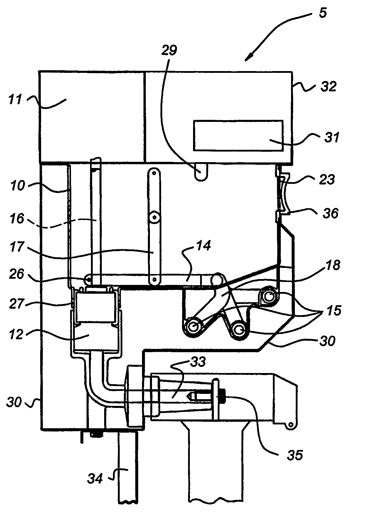
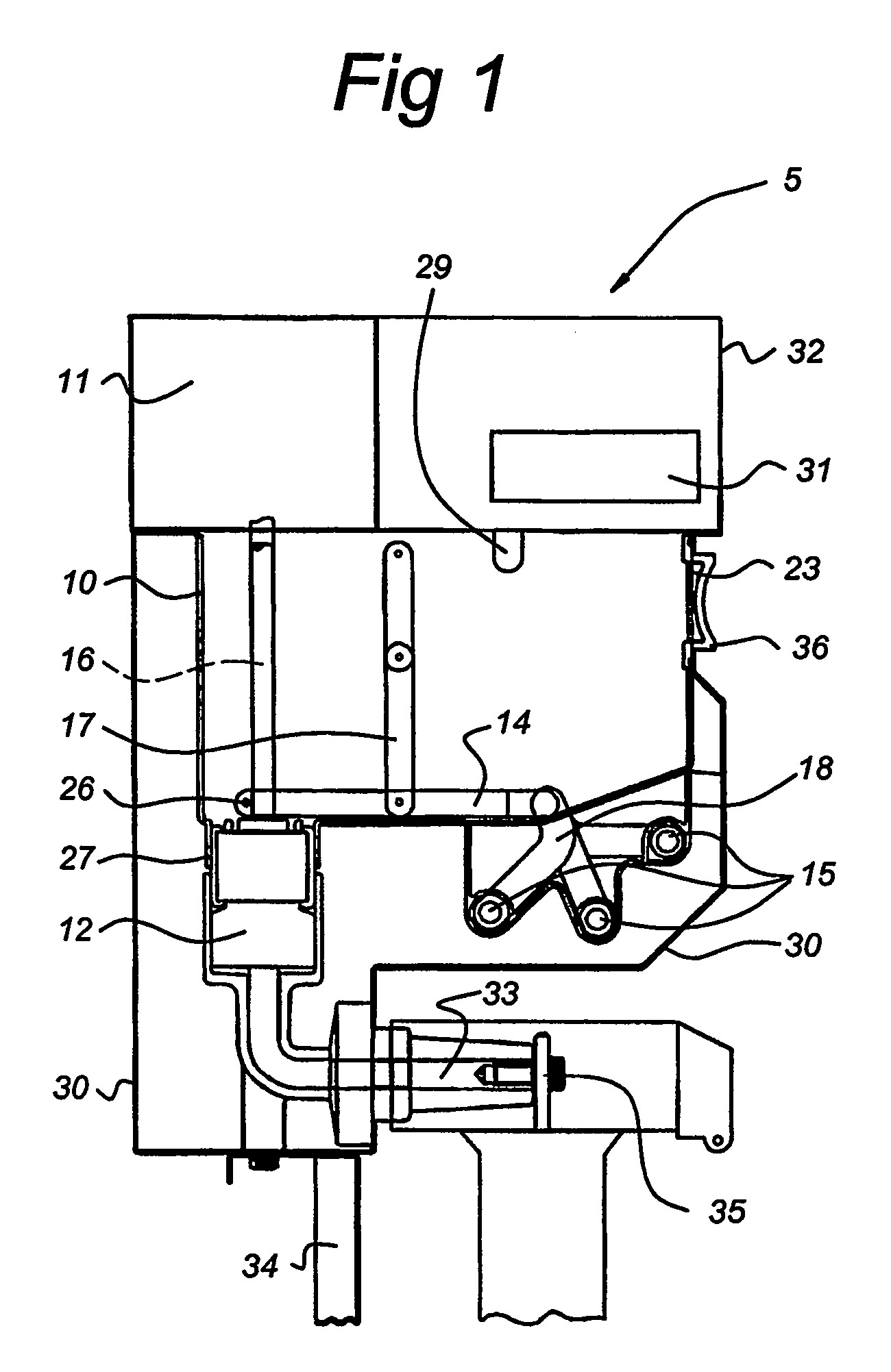
[0039]FIG. 1 shows a simplified cross-sectional view through an electrical switching installation 5 for medium or high voltage, in which an electrically insulating barrier 10 according to the invention is used. The switching installation 5 comprises a closed casing 30 made from metal, inside which the elements of the switching installation 5 are located. The casing 30 is mounted on a securing frame 34. In the example shown, the switching installation 5 is used to make or break an electrical connection between a power supply line 35, which is connected to a cable connection 33, and one of the rails 15 of a three-phase rail system. A conductor leads from the cable connection 33 to a bottom connection of a circuit breaker 12, in the form of a vacuum circuit breaker, which is actuated by a drive rod 16. In the switching installation 5, the circuit breaker 12 is used to switch currents on and off. The other connection of the circuit breaker 12 is connected, in the example shown, via a sl...


PUM


Abstract

A switching installation (5) having a circuit breaker (12), which is connected to a cable connection (33), and optionally a disconnector (14) for making or breaking a conductive connection between the cable connection (33) and a rail system (15), and an electrically insulating barrier (10). The electrically insulating barrier (10) surrounds at least the parts which are under electric voltage in operation from the circuit breaker (12) to the rail system (15), including a branch (18) leading to a rail (15) of the rail system, separately for each phase of the switching installation (5). Furthermore, inside the electrically insulating barrier (10) the switching installation may be provided with field-control means and/or voltage-sealing means (22, 25, 37).

Description

BACKGROUND OF THE INVENTION[0001]1. Field of the Invention[0002]The present invention relates to a switching installation, suitable in particular for voltages of over 1000 V, comprising a circuit breaker, which is connected to a cable connection, and optionally a disconnector for making or breaking a conductive connection between the cable connection and a rail system, and an electrically insulating barrier for shielding an element of the switching installation which is under voltage in operation.[0003]More in particular, this invention relates to a switching installation according to the preamble of claim 1.[0004]2. Background Information[0005]Such a switching installation is known from patent publication CH-A-200 798.[0006]Since most switching installations are of three-phase design, there are also three of each of the abovementioned components per functional unit (also referred to as a field), these components being physically and electrically separated from one another for each ...

Claims


Application Information

Patent Timeline
Patent Type & Authority Patents(United States)
IPC IPC(8): H02B1/14H02B3/00H01H31/00H01H33/02H01H33/66H02B1/32H02B13/02H02B13/065
CPCH01H33/022H02B13/02H01H31/003H01H33/6661H01H2033/566H01H2033/6623H01H2009/0292
Inventor LAMMERS, AREND JAN WILLEM
Owner EATON ELECTRIC INC
Why Eureka
Try Eureka