Integrated crossed roller bearing for harmonic speed reducer

A technology of cross roller bearings and harmonic reducers, which is applied in the direction of rolling contact bearings, bearings, flexible bearings, etc., can solve the problems of the overall structure of the harmonic reducer, which is not compact enough, requires high positional relationship, and occupies a large space, and achieves The effect of compact structure, small moment of inertia, and smaller occupied space

Inactive Publication Date: 2015-08-19
郭利平
View PDF0 Cites 1 Cited by
  • Summary
  • Abstract
  • Description
  • Claims
  • Application Information

AI Technical Summary

Problems solved by technology

[0003] With the continuous deepening of the application field, compact, precise, stable rotation technical requirements, and the general trend of energy saving and emission reduction, the existing harmonic reducer adopts external cross roller bearings, and the overall structure of the harmonic reducer is not compact enough. The structure is too large, the weight is too heavy, and it takes up a lot of space. The use of external cross roller bearings makes more related parts, related assembly, high positional relationship requirements, and complex mechanisms; Larger and heavier, so that the moment of inertia is large, so under the same output force, the structure is large and the energy consumption is high

Method used


Image

  • Integrated crossed roller bearing for harmonic speed reducer

Examples


Embodiment Construction

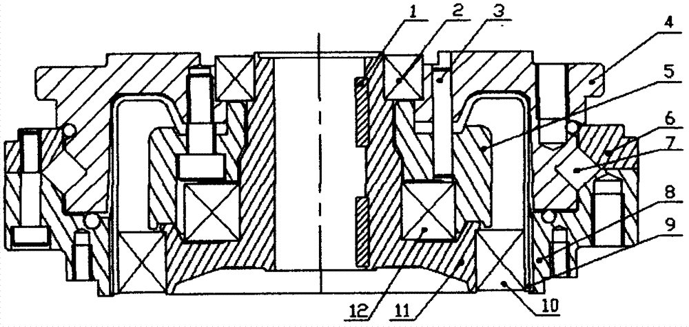
[0012] The present invention is described below in conjunction with accompanying drawing.

[0013] attached figure 1 A harmonic reducer adopts an integrated cross roller bearing structure, including key 1, bearing 2, pin 3, flex spline gland 4, support block 5, adjustment block 6, roller 7, steel wheel 8, flex spline 9. Flexible bearing 10, input shaft (wave generator) 11, bearing 12; it is characterized in that, the flexspline gland 4 is closely connected with the flexspline 9, connected with the input shaft 11 through the bearing 2, and the flexspline gland 4 The inner ring of the crossed roller bearing is composed; the steel wheel 8 and the flexspline 9 are meshed with the flexspline to transmit power through the tooth structure; the adjusting block 6 and the steel wheel 8 are composed of the outer ring of the crossed roller bearing. Adopting the integrated design feature, the flexspline gland 4 is not only the input (or output) part of the flexspline 9, but also the inner...


PUM


Abstract

The invention discloses an integrated crossed roller bearing for a harmonic speed reducer. The integrated crossed roller bearing comprises the harmonic speed reducer, an input shaft, a flexible wheel, a steel wheel, a flexible wheel gland, a roller and an adjusting block. The flexible wheel gland, the adjusting block, the steel wheel and the roller form a pair of complete crossed roller bearing structures, and the pair of complete crossed roller bearing structures is connected with a flexible wheel end cover, a rigid wheel and other components of the harmonic speed reducer instead of the traditional external independent crossed roller bearing; the flexible gland is precisely connected with the flexible wheel, is connected with the input shaft by a bearing and forms an inner ring of the crossed roller bearing; the adjusting block and the steel wheel form an outer ring of the crossed roller bearing, the steel wheel is meshed with the flexible wheel by a serrated structure, and accordingly power can be transmitted; the flexible wheel gland not only is an input (or output) component of the flexible wheel, but also is the inner ring of the crossed roller bearing; the steel wheel is meshed with the flexible wheel by the serrated structure, accordingly, the power can be transmitted, and the steel wheel and the adjusting block are combined with each other to form the outer ring of the crossed roller bearing. Compared with the traditional external crossed roller bearing connected with an existing flexible wheel gland and an existing steel wheel, the integrated crossed roller bearing with integral structural characteristics has the advantages of simple and compact structure, small rotation radiuses and rotational inertia, good rigidity, few consumed materials, low integral weight, reliability and accuracy in transmission, stability in running and the like.

Description

technical field [0001] The invention relates to a cross roller bearing structure, in particular to a cross roller bearing structure used in a compact harmonic reducer Background technique [0002] The harmonic reducer is mainly composed of three basic components: a wave generator, a flexible gear and a rigid gear. Gear transmission to transmit motion and power. In the harmonic reducer, the connection between the flex spline gland and the steel wheel often uses an external cross roller bearing. [0003] With the continuous deepening of the application field, compact, precise, stable rotation technical requirements, and the general trend of energy saving and emission reduction, the existing harmonic reducer adopts external cross roller bearings, and the overall structure of the harmonic reducer is not compact enough. The structure is too large, the weight is too heavy, and it takes up a lot of space. The use of external cross roller bearings makes more related parts, related...

Claims


Application Information

Patent Timeline
IPC IPC(8): F16H57/021F16C27/00F16C27/04
CPCF16H57/021F16C27/00F16C27/04
Inventor 郭利平
Owner 郭利平
Why Eureka
Try Eureka