Method for using a hydraulic amplifier pump in ultrahigh pressure liquid chromatography

a technology of amplifier pump, which is applied in the direction of piston pump, positive displacement liquid engine, instrument, etc., can solve the problems of inability to create the pressure required for ultra-high pressure liquid chromatography (uhplc), difficulty in implementing at the low flow rate used in uhplc, etc., and achieves constant flow rate and sufficient pressure

Active Publication Date: 2007-12-25
WATERS TECH CORP
View PDF8 Cites 63 Cited by
  • Summary
  • Abstract
  • Description
  • Claims
  • Application Information

AI Technical Summary

Benefits of technology

[0005]The present invention provides a pump that can generate sufficient pressure and that create...

Problems solved by technology

These pumps, which typically use mechanical mechanisms to actuate flow-generating pistons, cannot create the pressures required for ultra-high pressure liquid chromatography (UHPLC), which operates at pressures in excess of 25,000 psi.
However, since the gas in pneumatic amplifiers is compressible, pneumatic amplifiers can deliver only constant pressure flow, which precludes high pressure gradient mixing necessary to perform gradien...

Method used


Image

  • Method for using a hydraulic amplifier pump in ultrahigh pressure liquid chromatography
  • Method for using a hydraulic amplifier pump in ultrahigh pressure liquid chromatography
  • Method for using a hydraulic amplifier pump in ultrahigh pressure liquid chromatography

Examples


Embodiment Construction

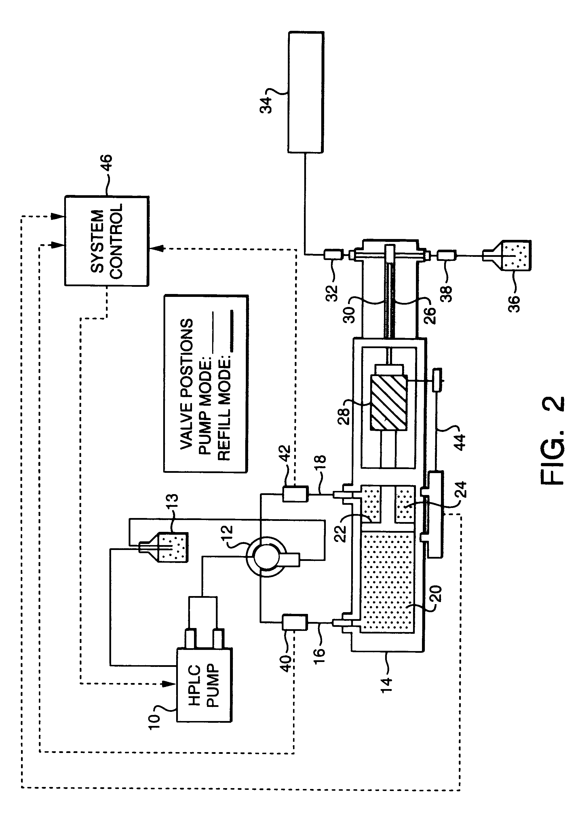
[0014]FIG. 2 shows a schematic of a single hydraulic amplifier system according to the invention. The system comprises HPLC pump 10 which pumps hydraulic fluid through a multi-port HPLC rotary valve 12 into a hydraulic cylinder 14 at a constant flow rate. Excess hydraulic fluid is stored in a hydraulic fluid reservoir 13. The position of the multi-port valve 12 determines whether the hydraulic fluid flows through an inlet valve 16 or outlet valve 18 so as to control whether the HPLC pump operates in “Pump Mode” or “Refill Mode.” In the “Pump Mode,” hydraulic fluid from the HPLC pump 10 is directed into an inlet chamber 20 of the hydraulic cylinder 14, which displaces a primary piston 22 in a first direction (which in FIG. 2 is to the right). In the “Refill Mode,” the hydraulic fluid is directed into an outlet chamber 24, thereby displacing the primary piston 22 in a second direction (which in FIG. 2 is to the left). The primary piston 22 is coupled to a secondary piston 26 through a...


PUM


Abstract

A method for supplying solvent to an ultra-high pressure liquid chromatography system using a hydraulic amplifier. The hydraulic amplifier system includes a hydraulic cylinder comprising a primary piston chamber in which a primary piston is disposed and a secondary piston chamber in which a secondary piston is disposed. The cross-sectional area of the primary piston is larger than the cross-sectional area of the secondary piston. The difference in the cross-sectional areas of the pistons creates an amplification of the pressure in the primary piston chamber and a reduction in flow rate.

Description

CROSS REFERENCE TO RELATED APPLICATIONS[0001]This application is a continuation of application Ser. No. 10 / 026,089 filed Dec. 21, 2001, now U.S. Pat. No. 6,712,587. The contents of the aforementioned application are hereby expressly incorporated herein by reference in its entirety.FIELD OF THE INVENTION[0002]The present invention relates to a pump for ultra-high pressure liquid chromatography, and more particularly to a pump to generate the high pressure and low flow rates required for ultra-high pressure liquid chromatography.BACKGROUND OF THE INVENTION[0003]Pumps used in typical high pressure liquid chromatography (HPLC) generate approximately 5000 psi. These pumps, which typically use mechanical mechanisms to actuate flow-generating pistons, cannot create the pressures required for ultra-high pressure liquid chromatography (UHPLC), which operates at pressures in excess of 25,000 psi. Pneumatic amplifiers have been used to generate high pressures for UHPLC systems. For example, in...

Claims


Application Information

Patent Timeline
IPC IPC(8): F04B17/00F04B49/06F04B9/103F04B9/117F04B23/06
CPCF04B9/113F04B9/1174F04B9/1178F04B13/00F04B23/06G01N30/22G01N30/32F04B49/065G01N2030/326G01N30/34G01N30/36G01N2030/324
Inventor GERHARDT, GEOFF C.COMPTON, BRUCE J.
Owner WATERS TECH CORP
Why Eureka
Try Eureka