Micro coaxial cable connector assembly

Inactive Publication Date: 2007-12-25
HON HAI PRECISION IND CO LTD
View PDF14 Cites 25 Cited by
  • Summary
  • Abstract
  • Description
  • Claims
  • Application Information

AI Technical Summary

Benefits of technology

[0006]Accordingly, one object of the present invention is to provide a low profile micro coaxial ca

Problems solved by technology

However, if conductors of wires are so slim that they are may be badly damaged when urged into the termination sections.
However, the grounding means of this kind of cable connector assembly is relatively complex in structure and costly in manu

Method used


Image

  • Micro coaxial cable connector assembly
  • Micro coaxial cable connector assembly
  • Micro coaxial cable connector assembly

Examples


Embodiment Construction

[0025]Reference will now be made in detail to the preferred embodiment of the present invention.

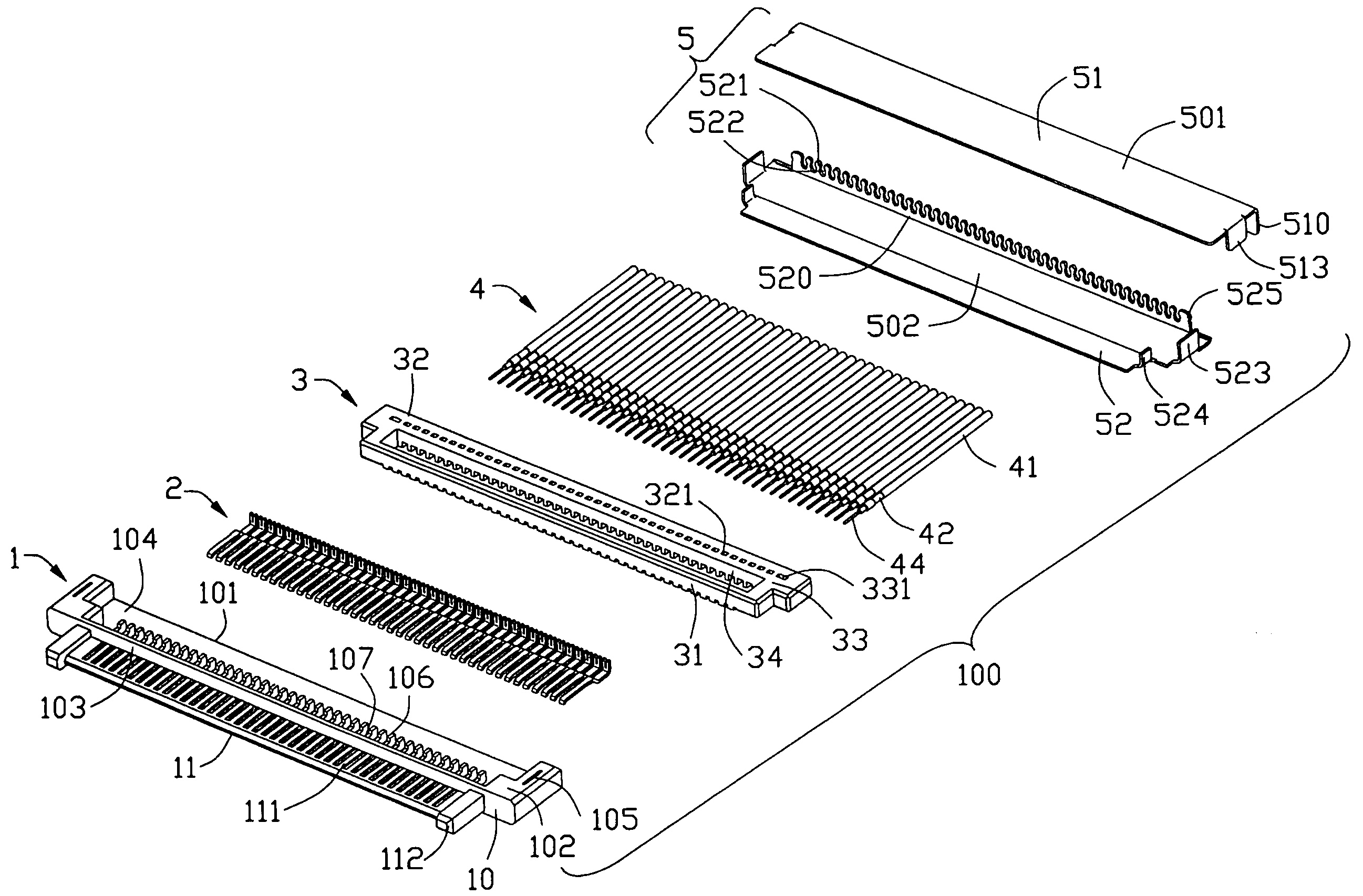
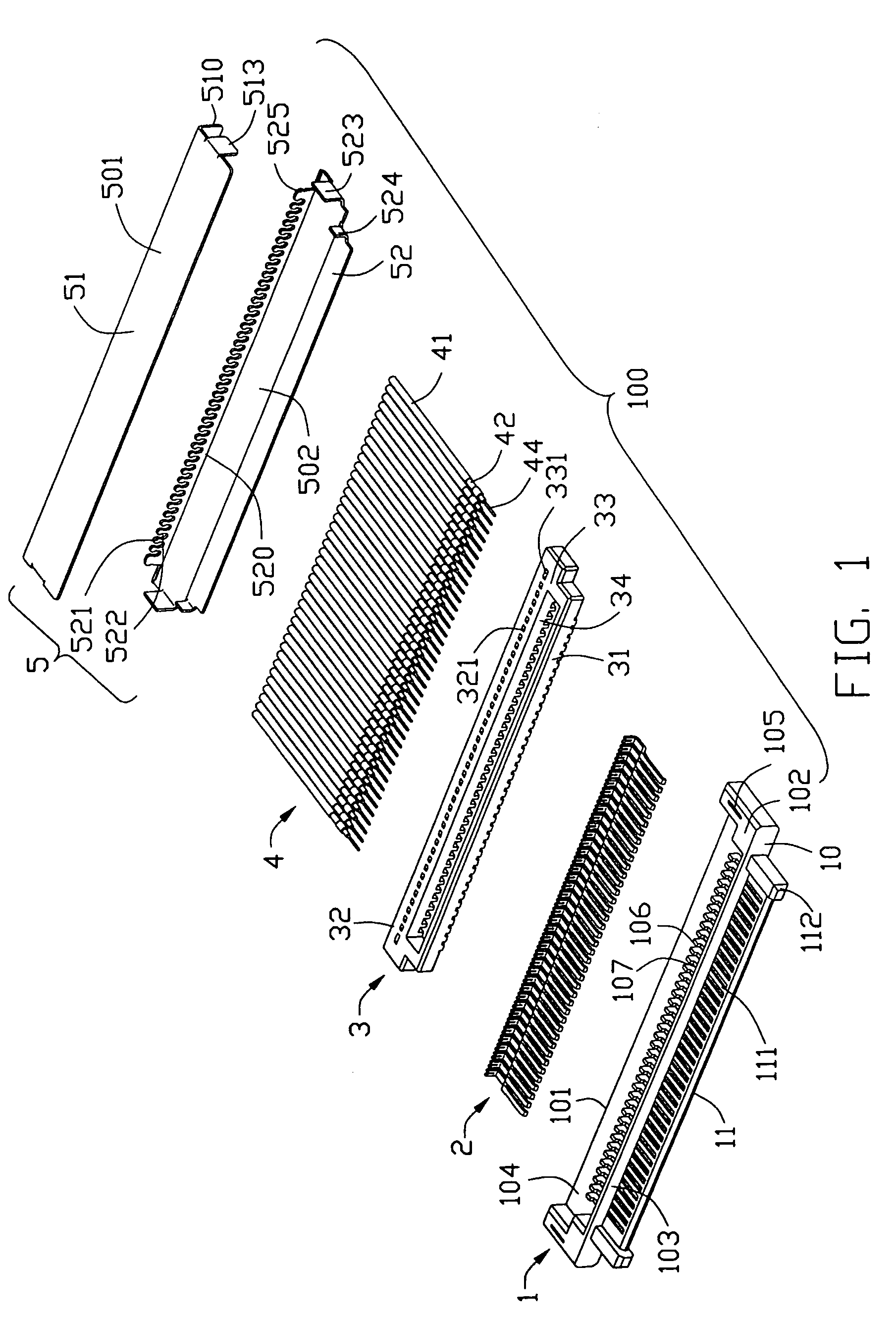
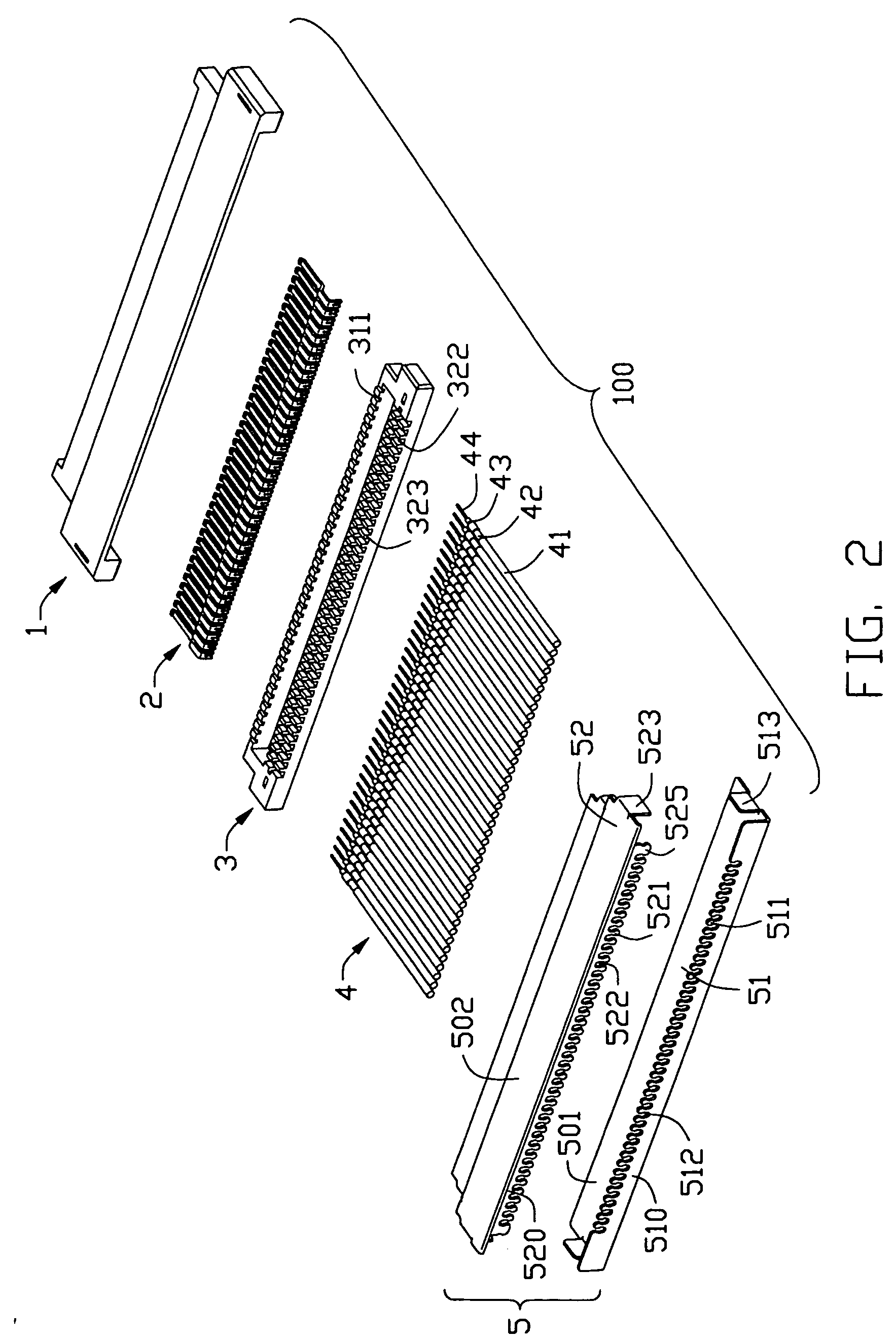
[0026]Referring to FIGS. 1-3, a micro coaxial electrical connector assembly 100 in accordance with the first embodiment of the present invention comprises an insulated housing 1, a plurality of contacts 2 arranged in a row along a transversal direction and received in the insulated housing 1, a number of coaxial wires 4 electrically connecting to the contacts 2, a wire spacer 3 used for positioning the coaxial wires 4 and a metal shell 5 shielding the insulated housing 1.

[0027]The insulated housing 1 comprises a base portion 10 and a matching portion 11 extending forwardly from the base portion 10. The matching portion 11 is composed of a tongue portion 111 and a pair of guiding posts 112 integrally formed at lateral sides of the tongue portion 111 respectively. Each guiding post 112 forms with tapered forward end for facilitating the insertion of the micro coaxial connector assembly 100 ...


PUM


Abstract

A micro coaxial cable connector assembly (100) including an insulated housing (1), a plurality of contacts (2) received in the insulated housing (1), a number of coaxial wires (4) soldered to the contacts (2), a wire spacer (3) used for positioning the coaxial wires (4) and a metal shell (5) assembled to the insulated housing (1) to reduce EMI. The connecting portions and rear portions of the contacts are placed in the slots (107) of the insulated housing (1) forming a plurality of soldering areas. The coaxial wires (4) are soldered to the contacts (2) with conductors held by the cutouts of the rear portions of the contacts (2) and placed in the soldering areas.

Description

BACKGROUND OF THE INVENTION[0001]1. Field of the Invention[0002]The present invention generally relates to a cable connector assembly, and more particularly to a micro coaxial cable connector assembly having a relatively low profile and multi-pitch contacts.[0003]2. Description of Related Art[0004]A micro coaxial cable connector is widely used in the high frequency communication connector field and is required to terminate a coaxial multiconductor wires. Because of its wide use, designers have designed different structures to satisfy different applications. For example, U.S. Pat. No. 5,766,033 discloses a high density electrical connector. The electrical connector having a housing molded around body sections of a plurality of terminals disposed in first and second rows. The terminals have IDC termination sections for respective wires to be urged thereinto by termination covers. Those IDC termination sections of the first row are staggered rearwardly from those IDC termination sectio...

Claims


Application Information

Patent Timeline
IPC IPC(8): H01R9/05H01R12/55
CPCH01R4/023H01R4/027H01R23/662H01R12/592H01R12/777H01R9/0524H01R12/775
Inventor KO, DAVID TSO-CHIN
Owner HON HAI PRECISION IND CO LTD
Why Eureka
Try Eureka