Plasma-generation power-supply device

a power supply device and plasma technology, applied in the direction of electric variable regulation, process and machine control, instruments, etc., can solve the problems of large size and increased cost of the power supply device, no guarantee of the most suitably driven load, and the power dissipation of the power supply becomes maximum, so as to achieve stable operation

Inactive Publication Date: 2007-12-25
MITSUBISHI ELECTRIC CORP
View PDF16 Cites 46 Cited by
  • Summary
  • Abstract
  • Description
  • Claims
  • Application Information

AI Technical Summary

Benefits of technology

[0018]The present invention has been made to solve the above problems, and an object of the invention is to provide a plasma-generation power-supply device that is capable of driving with a power factor as high as possible under a maximum rated condition and of keeping stable operation even when the applied power is varied.
[0020]According to the plasma-generation power-supply device, the controller provides control to vary the power-supply frequency of the alternating-current power-supply in accordance with the target applied power to the discharging load. Accordingly, when the maximum rated power is applied, the frequency of the alternating-current power-supply is set close to the resonant frequency of the load to achieve driving operation with a high power factor, so that the capacity of the alternating-current power-supply can be reduced, and the frequency is set higher when the applied power is smaller, so as to achieve stable control of the discharge.
[0024]According to the plasma-generation power-supply device, the alternating-current power-supply is connected electrically directly to the resonance means, and the output voltage of the alternating-current power-supply is made to jump by resonance and given to the discharging load, which eliminates a need for, e.g., an expensive high-frequency transformer, and allows cost reduction.

Problems solved by technology

Therefore, the elements forming the transformer and the inverter need specifications capable of withstanding such current value, which leads to large-sizing and increased costs of the power-supply device.
This is certainly an effective method, but is disadvantageous when the capacity of the power-supply is to be minimized by making the power factor as high as possible when maximum power is applied and the power dissipation of the power-supply becomes maximum.
There is no guarantee that the load can be driven most suitably in such cases.
Also, even if the electrostatic capacity of the discharging load is strictly constant, the resonance condition depends on the applied power and therefore adjusting the applied power inevitably varies the resonance condition, and the driving condition deviates from the most suitable state.
Furthermore, when the maximum rated power is being applied and the load is driven with a high power factor in the vicinity of the resonance point, decreasing the applied power makes the control of the power-supply or discharge unstable.

Method used


Image

  • Plasma-generation power-supply device
  • Plasma-generation power-supply device
  • Plasma-generation power-supply device

Examples


Embodiment Construction

[0058]

[0059]

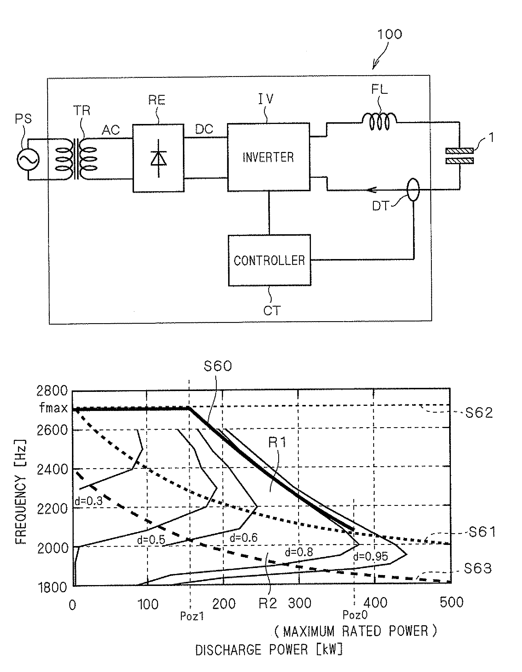
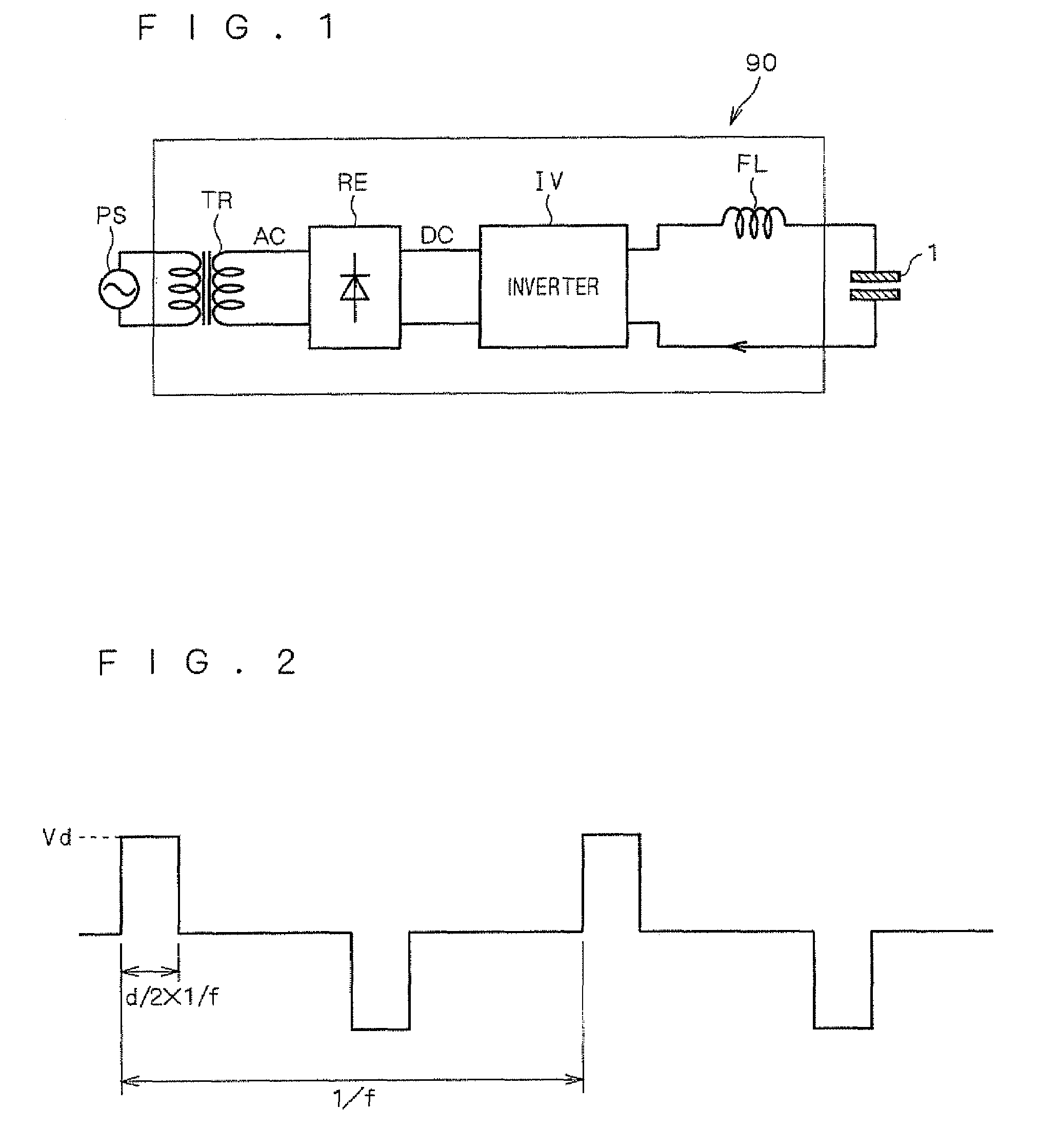
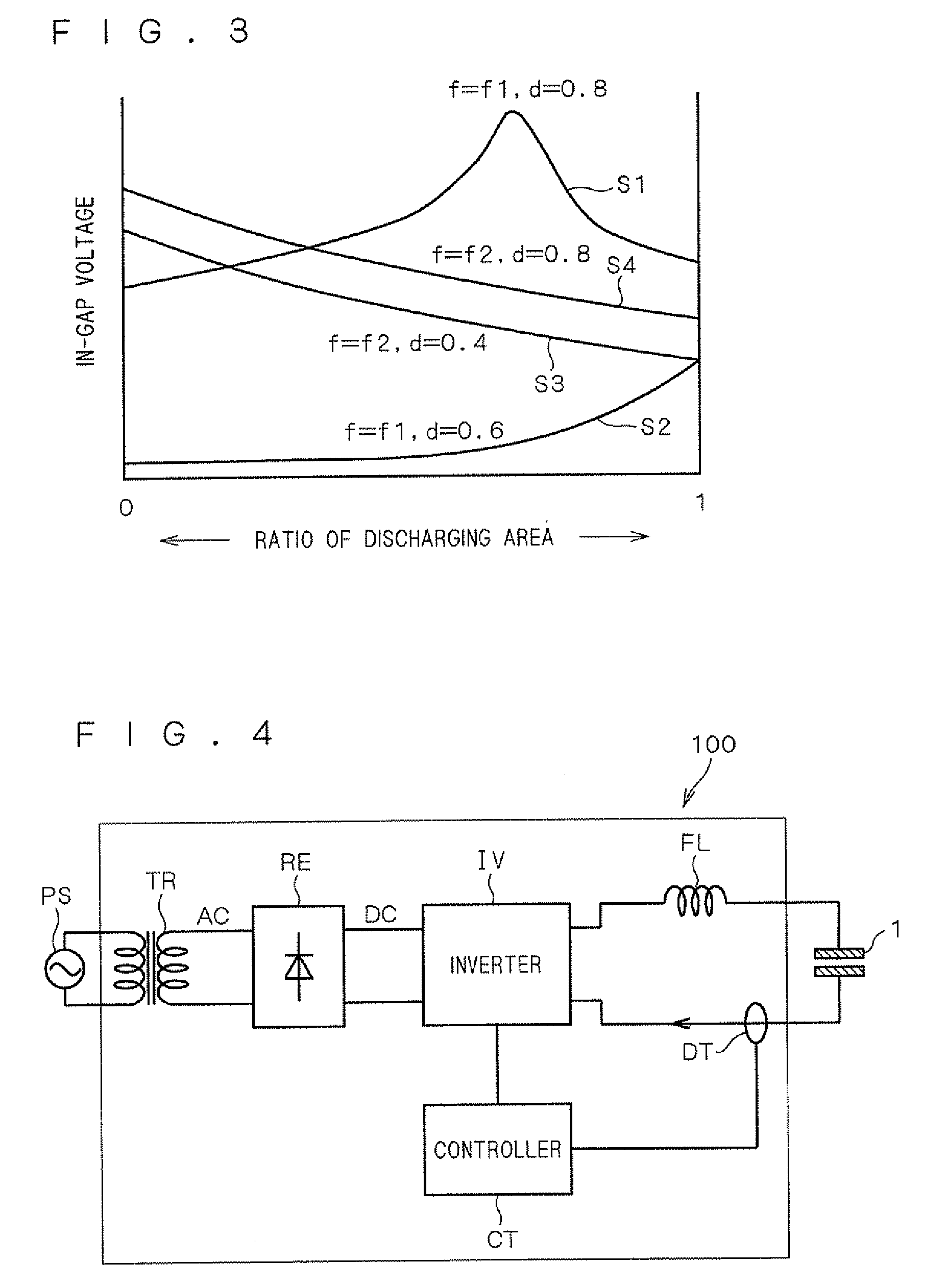
[0060]First, a plasma-generation power-supply device 90 having a simplified configuration will be described referring to FIGS. 1 to 3, in order to describe the basic operation of the power-supply device according to a first preferred embodiment of the present invention.

[0061]As shown in FIG. 1, the plasma-generation power-supply device 90 includes a transformer TR connected to an alternating-current power-supply PS as a power source, a rectifier RE connected to the transformer TR, an inverter IV (alternating-current power-supply) connected to the rectifier RE, and a reactor FL (resonance means) inserted in series in the power line of an ozonizer 1 that is supplied with power from the inverter IV. The inverter IV is connected electrically directly to the reactor FL. Connecting the inverter IV electrically directly to the reactor FL means that the output of the inverter IV is connected to the reactor FL not through magnetic transmission means such as a transformer, but thr...


PUM

PropertyMeasurementUnit
frequencyaaaaaaaaaa
frequencyaaaaaaaaaa
frequencyaaaaaaaaaa

Abstract

A plasma-generation power-supply device includes a transformer connected to an alternating-current power-supply, a rectifier connected to the transformer, an inverter connected to the rectifier, a reactor inserted in series in a power line of an ozonizer that is supplied with power from the inverter, and a controller that controls the inverter. The controller detects the current flowing to the ozonizer with a current detector and provides a control that keeps power applied to the ozonizer constant.

Description

[0001]This Application is a National Phase Application under 35 U.S.C. 371 claiming the benefit of PCT / JP04 / 1 5362 filed on Oct. 18, 2004, which has priority based on Japan Application No. 2004-095248 filed on Mar. 29, 2004.TECHNICAL FIELD [0002]The present invention relates to a power-supply device for use in generation of plasma, and particularly to a power-supply device for use in plasma generation with an ozonizer, flat-plate light source, laser oscillator, and the like.BACKGROUND ART [0003]In a discharge system called dielectric barrier discharge or silent discharge, an alternating voltage is applied to oppositely placed electrodes with the high-potential electrode covered with a dielectric, so as to cause a discharge. This type of discharge is used in a wide variety of industrial applications that utilize chemical reactions with plasmas, because the discharge does not change to an arc and the electron temperature is stably kept high.[0004]A particularly typical application the...

Claims


Application Information

Patent Timeline
Patent Type & Authority Patents(United States)
IPC IPC(8): H05B41/16H05B37/02C01B13/11H01J37/32H01L21/3065H01T23/00H05B41/28H05H1/24H05H1/46
CPCC01B13/11C01B13/115H01J37/32009H01J37/32348H05B41/2806H05H1/46C01B2201/14C01B2201/22C01B2201/62Y02B20/22G09G3/2965C01B2201/64Y02B20/00
Inventor TAMITA, TAICHIROIWATA, AKIHIKOWADA, NOBORUMINE, SHINGONAKATANI, HAJIME
Owner MITSUBISHI ELECTRIC CORP
Why Eureka
Try Eureka