Model railroad velocity controller

a controller and model technology, applied in the direction of programme control, instrumentation, dynamo-electric converter control, etc., can solve the problems of increasing the voltage and thus the power available, physical manipulation of the control knob, and delay the response between the train speed and the controller, so as to control the velocity of the model train, shorten the elapsed time between pulses, and increase the power communicated to the train

Active Publication Date: 2007-12-25
WACHOVIA BANK N A ADMINISTRATIVE AGENT
View PDF24 Cites 21 Cited by
  • Summary
  • Abstract
  • Description
  • Claims
  • Application Information

AI Technical Summary

Benefits of technology

[0014]Control over velocity of a model train may be determined based upon the speed of rotation of a control knob. A processor receives an electronic pulse indicating rotation of the knob beyond a predetermined increment of angular distance. The processor calculates the amount of power ultimately conveyed to the model train based not only upon the number of pulses received, but also upon the elapsed time between these pulses. The shorter the elapsed time between pulses, the g

Problems solved by technology

This in turn increases the voltage and thus the power available to operate the model train.
First, the extra time required to rotate the knob an additional distance may delay respons

Method used


Image

  • Model railroad velocity controller
  • Model railroad velocity controller
  • Model railroad velocity controller

Examples


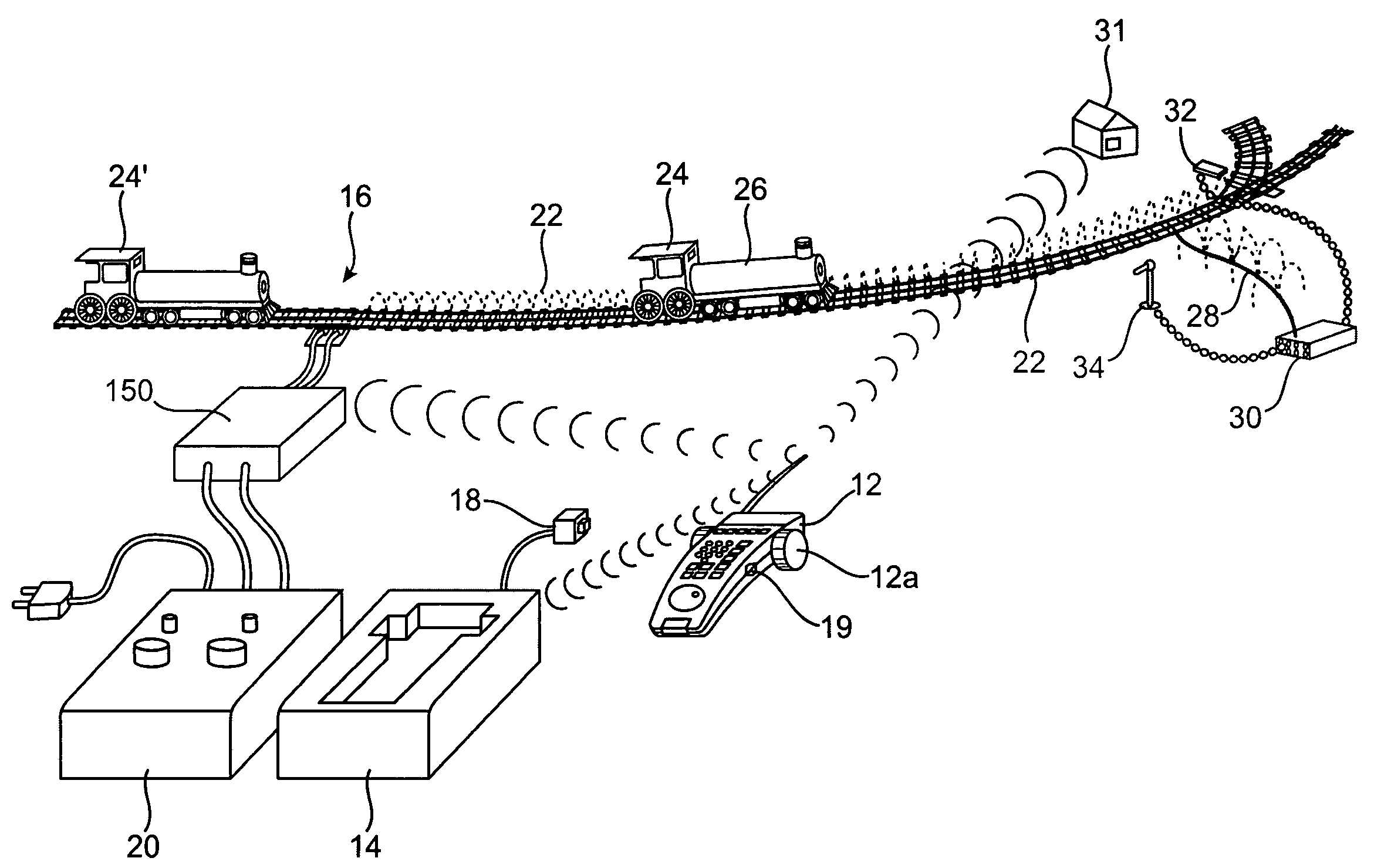
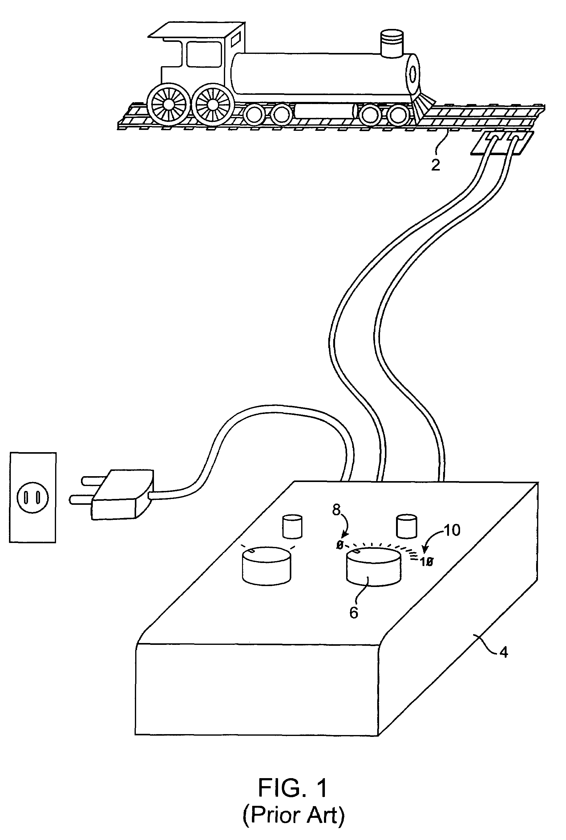
example train layout

[0058]FIG. 4 is a perspective drawing of an example layout of an alternative train track system. A hand-held remote control unit 12 including control knob 12a is used to transmit signals to a base unit 14 and to a power master unit 150, both of which are connected to train tracks 16. Base unit 14 receives power through an AC adapter 18. A separate transformer 20 is connected to track 16 to apply power to the tracks through power master unit 150. Power master unit 150 is used to control the delivery of power to the track 16 and also is used to superimpose DC control signals on the AC power signal upon request by command signals from the hand-held remote control unit 12.

[0059]Power master unit 150 modulates AC track power to the track 16 and also superimposes DC control signals on the track to control special effects and locomotive 24′. Locomotive 24′ is, e.g., a standard Lionel locomotive powered by AC track power and receptive to DC control signals for, e.g., sound effects.

[0060]Bas...


PUM


Abstract

Control over velocity of a model train may be determined based upon the speed of rotation of a control knob. A processor receives electronic pulses indicating rotation of the knob beyond a predetermined increment of angular distance. The processor calculates the amount of power ultimately conveyed to the model train based not only upon the number of pulses received, but also upon the elapsed time between these pulses. The shorter the elapsed time between pulses, the greater the change in power communicated to the train. Initially, a user can rapidly rotate the knob to attain coarse control over a wide range of velocities, and then rotate the knob more slowly to achieve fine-grained control over the coarse velocity. Utilizing the control scheme in accordance with embodiments of the present invention, in a compact and uninterrupted physical motion, a user can rapidly exercise both coarse and fine control over velocity of a model train.

Description

BACKGROUND OF THE INVENTION[0001]Model train systems have been in existence for many years. In the typical system, the model train engine is an electrical engine which receives power from a voltage which is applied to the tracks and picked up by the train motor. A transformer is used to apply the power to the tracks. The transformer controls both the amplitude and polarity of the voltage, thereby controlling the speed and direction of the train. In HO systems, the voltage is typically a DC voltage. In other systems, the voltage may be an AC voltage transformed from the 60 Hz line voltage available in a standard wall socket.[0002]A variety of mechanisms are used to control velocity of model trains. In the traditional approach shown in FIG. 1, application of power to track 2 by transformer 4 is regulated by twisting a control knob 6 approximately 90°, from a zero power position 8 to a full power position 10.[0003]FIG. 2 shows a simplified cut-away view of the internal components of th...

Claims


Application Information

Patent Timeline
IPC IPC(8): H02P1/00
CPCA63H19/24A63H30/04
Inventor KOVACH, II, LOUIS G.YOUNG, NEIL P.
Owner WACHOVIA BANK N A ADMINISTRATIVE AGENT
Why Eureka
Try Eureka