Mobile terminal positioning system

a mobile terminal and positioning system technology, applied in direction finders, instruments, measurement devices, etc., can solve the problems of difficult positioning of mobile radio terminal apparatus b>3/b> along a straight distance, multipath fading, and insufficient information about how to operate the system in practice, so as to increase the probability of detection of a first path, increase the accuracy, and increase the accuracy

Inactive Publication Date: 2007-12-25
NEC CORP
View PDF6 Cites 4 Cited by
  • Summary
  • Abstract
  • Description
  • Claims
  • Application Information

AI Technical Summary

Benefits of technology

[0022]It is an object of the present invention to provide a mobile terminal positioning system, a radio base station apparatus and a mobile terminal positioning method for use therein, and a program therefor, which are capable of increasing the probability of detection of a first path even if a radio transmission path fluctuates due to fading or the like, and of downsizing and reducing the cost of mobile radio terminal apparatus.
[0037]Even if it is difficult to detect a path arriving from the mobile radio terminal apparatus due to fading or like caused in a radio zone, the mobile terminal positioning system according to the present invention reduces an error occurring when the arrival time of a signal between the radio base station apparatus and the mobile radio terminal apparatus is estimated.
[0041]The mobile terminal positioning system according to the present invention thus has a function to set a threshold value for a path search depending on the reception SIRs. If the SIR is higher, then the threshold value is set to a higher value to prevent a path from being detected in error, and if the SIR is lower, then the threshold value is set to a lower value in order to be able to catch a path. Therefore, the probability of detection of a first path is increased even if the radio transmission path fluctuates due to fading or the like.
[0042]Furthermore, with the mobile terminal positioning system according to the present invention being incorporated in the radio base station apparatus, the circuit arrangement of the mobile radio terminal apparatus is minimized, thereby downsizing and reducing the cost of the mobile radio terminal apparatus.
[0043]Moreover, inasmuch as the mobile terminal positioning system according to the present invention employs multi-carrier modulation that is supposed to be resistant to multipath fading, signal degradation, at the time upload pilot signals from the mobile radio terminal apparatus are demodulated, is reduced, so that the accuracy with which to estimate SIRs is improved.

Problems solved by technology

However, the above mobile communication system with the positioning capability is problematic in that since no specific examples of the modulation process, etc. are not shown, there is not much information about how to operate the system in practice.
Furthermore, the above mobile communication system with the positioning capability is disadvantageous in that it tends to cause a propagation time error.
Particularly in an urban area, shadowing occurs due to buildings or the like, and reflections from other directions reach radio base station 4 and cause multipath fading, making it difficult to position mobile radio terminal apparatus 3 along a straight distance.
However, the above conventional mobile terminal positioning system as it is incorporated in the mobile radio terminal apparatus is problematic in that the mobile radio terminal apparatus tends to be complex and large in size.
Another problem of the conventional mobile terminal positioning system is that the accuracy of a path search is lowered depending on the propagation environment.
In the actual environment of a cellular phone radio network, however, received signals fluctuate and are attenuated by fading.
When the reception SIR is low, there is a tendency for a higher probability of burial of a path in noise.
If the set threshold value is too high, then a path may not possibly be detected.
Conversely, if the set threshold value is too low, then noise may easily be detected in error as a path.
If the same threshold value is set as when the reception SIR is high, then it is difficult to detect a proper first path due to the propagation environment.

Method used


Image

  • Mobile terminal positioning system
  • Mobile terminal positioning system
  • Mobile terminal positioning system

Examples


Embodiment Construction

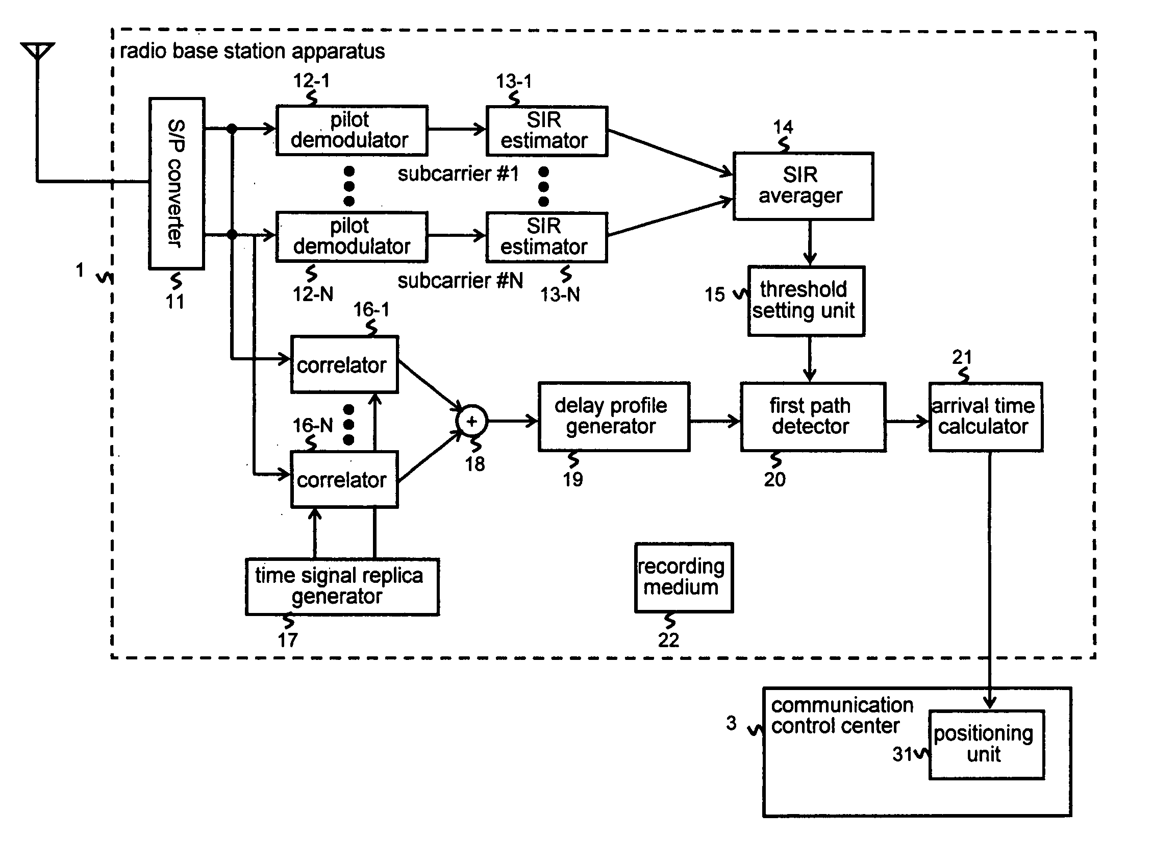
[0050]An embodiment of the present invention will be described below with reference to the drawings. FIG. 3 is a block diagram of a radio base station apparatus according to an embodiment of the present invention. As shown in FIG. 3, radio base station apparatus 1 comprises S / P (Serial / Parallel) converter 11, pilot demodulators 12-1 through 12-N, SIR (Signal to Interference power Ratio) estimators 13-1 through 13-n, SIR averager 14, threshold value setting unit 15, correlators 16-1 through 16-N, time signal replica generator 17, adder 18, delay profile generator 19, first path detector 20, arrival time calculator 21, and recording medium 22. Radio base station apparatus 1 is connected to communication control center 3 having positioning unit 31. Recording medium 22 stores a program (a program that can be executed by a computer) for realizing various processing details in radio base station apparatus 1.

[0051]A received signal from a mobile radio terminal apparatus, not shown, is inpu...


PUM


Abstract

There is provided a radio base station apparatus which is capable of increasing the probability of detection of a first path even if a radio transmission path fluctuates due to fading or the like, and of downsizing and reducing the cost of mobile radio terminal apparatus. SIR estimators 13-1 through 13-N calculate reception SIRs for respective subcarriers from output signals from pilot demodulators 12-1 through 12-N. SIR averager 14 averages the SIRs for the respective subcarriers to calculate an SIR for the overall signal. Based on the calculated SIR, threshold value setting unit 15 sets a threshold value for a path search. First path detector 19 conducts a path search based on the threshold set by threshold value setting unit 15. Arrival time calculator 21 calculates an arrival time based on a first path detected by first path detector 19.

Description

TECHNICAL FIELD[0001]The present invention relates to a mobile terminal positioning system, a radio base station apparatus and a mobile terminal positioning method for use therein, and a program therefor, and more particularly to a positioning method using a cellular phone radio base station apparatus in a next-generation communication system.BACKGROUND ART[0002]The positioning technology is one of important applications in next-generation communication systems. Although the positioning technology has already put to practical use at present, it is necessary to discuss a process for positioning a mobile terminal in a next-generation communication system which is capable of high-speed download communications.[0003]As shown in FIG. 1, there is a process for positioning a mobile terminal using a radio base station apparatus based on a function for mobile radio terminal apparatus 3 to send back a signal that has been received from radio base station 4 through transmission path 100 (see, ...

Claims


Application Information

Patent Timeline
Patent Type & Authority Patents(United States)
IPC IPC(8): G01S1/24H04B1/707H04B1/7075H04W64/00
CPCH04W64/00
Inventor INABA, ARATA
Owner NEC CORP
Why Eureka
Try Eureka