Method and apparatus for controlling scanning of mosaic sensor array

a sensor array and mosaic technology, applied in the field of reconfigurable arrays of sensors, can solve the problems of difficult to produce electronics that would allow individual control over such small cells, limited control to larger structures, and inability to create larger cells that still perform well, etc., to achieve efficient scaling of the architecture, change the aperture configuration quickly, and retain flexibility

Inactive Publication Date: 2007-12-25
GENERAL ELECTRIC CO
View PDF31 Cites 143 Cited by
  • Summary
  • Abstract
  • Description
  • Claims
  • Application Information

AI Technical Summary

Benefits of technology

[0144]The various embodiments of the invention disclosed herein provide one or more of the following advantages: 1) fast configuration of arbitrary aperture patterns from one view to the next; 2) efficient programming of switch cells to minimize time and power requirements (e.g., by configuring only those switches that need to be changed from one view to the next); 3) the ability to translate aperture patterns quickly from view to view along the matrix axes while using minimum power; 4) the ability to change aperture configurations quickly between transmit and receive operations; 5) the ability to have multiple transmit / receive zones moving in different directions simultaneously; 6) programming of both transmit and receive switching configurations into the array); 7) definition of a region of interest that can be shifted along either or both array axes; 8) efficient scaling of architecture to large tiled arrays in view of: i) power constraints; ii) timing constraints; iii) retaining flexibility; and iv) minimizing complexity of configuration; 9) robustness to semiconductor defects; and 10) a fully programmable configuration of the switch matrix.

Problems solved by technology

It may not be possible to create larger cells that still perform well in terms of frequency response and sensitivity desired.
Unfortunately, it is difficult to produce electronics that would allow individual control over such small cells.
While in terms of the acoustical performance of the array as a whole, the small cell size is excellent and leads to great flexibility, control is limited to larger structures.
However, subelements comprise connected cells that are not switchably disconnectable and thus cannot be reconfigured.

Method used


Image

  • Method and apparatus for controlling scanning of mosaic sensor array
  • Method and apparatus for controlling scanning of mosaic sensor array
  • Method and apparatus for controlling scanning of mosaic sensor array

Examples


Embodiment Construction

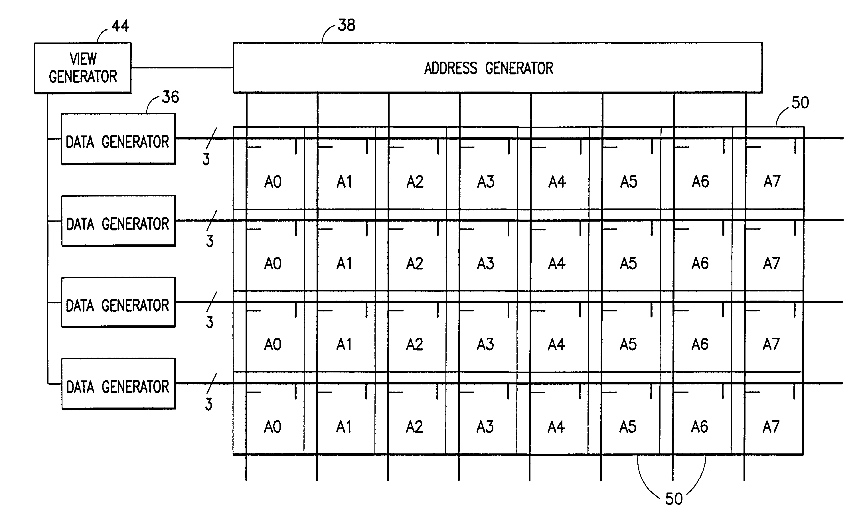
[0055]The invention is directed to a digital scanning architecture for controlling and configuring a reconfigurable switching matrix. For purposes of illustration, the reconfigurable array will be described with reference to capacitive micromachined ultrasonic transducers (cMUTs). However, it should be understood that the aspects of the invention disclosed herein are not limited in their application to probes employing cMUTs, but rather may also be applied to probes that employ pMUTs or even diced piezoceramic arrays where each of the diced subelements are connected by interconnect means to an underlying switching layer. The same aspects of the invention also have application in reconfigurable arrays of optical, thermal or pressure sensors.

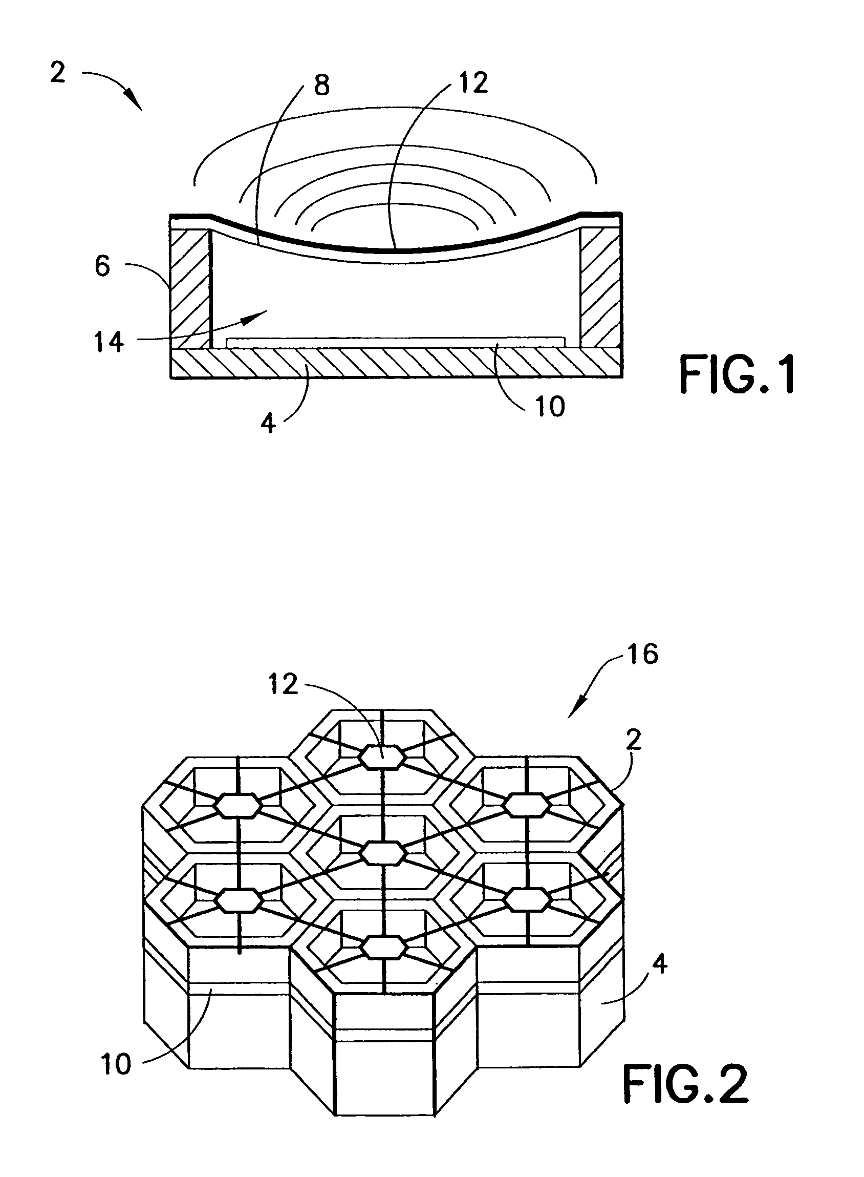
[0056]Referring to FIG. 1, a typical cMUT transducer cell 2 is shown in cross section. An array of such cMUT transducer cells is typically fabricated on a substrate 4, such as a heavily doped silicon (hence, semiconductive) wafer. For each cMUT tr...


PUM


Abstract

A scanning architecture that makes it possible to update only those ultrasonic transducer subelements of a mosaic transducer array that change from view to view. The configuration of the switch matrix is fully programmable. The switch matrix includes access switches that connect subelements to bus lines and matrix switches that connect subelements to subelements. Each subelement has a unit switch cell associated therewith, each unit switch cell comprising at least one access switch, at least one matrix switch, and addressing and control logic. Optionally, each unit switch cell also includes latches for storing the future switch states of the switches to be programmed. The switches themselves have memory for storing their current switch states.

Description

RELATED PATENT APPLICATION[0001]This application is a continuation-in-part of and claims priority from U.S. patent application Ser. No. 10 / 248,968, now U.S. Pat. No. 6,836,159 and U.S. patent application Ser. No. 10 / 383,990, now U.S. Pat. No. 6,865,140, both filed on Mar. 6, 2003.STATEMENT REGARDING FEDERALLY SPONSORED RESEARCH AND DEVELOPMENT[0002]The United States Government may have certain rights in this invention pursuant to U.S. Government Contract Number DAMD17-02-1-0181 awarded by the U.S. Army.BACKGROUND OF THE INVENTION[0003]This invention generally relates to reconfigurable arrays of sensors (e.g., optical, thermal, pressure, ultrasonic). In particular, the invention relates to a digital scanning architecture for control and configuration of a reconfigurable array of sensors.[0004]Conventional ultrasound imaging systems comprise an array of ultrasonic transducers that are used to transmit an ultrasound beam and then receive the reflected beam from the object being studied...

Claims


Application Information

Patent Timeline
Patent Type & Authority Patents(United States)
IPC IPC(8): H04R17/00G01S7/521B06B1/06H03K17/10H03K17/687
CPCA61B8/13H03K17/6874H03K17/102B06B1/0625B06B1/0292H03K17/687
Inventor WODNICKI, ROBERT GIDEON
Owner GENERAL ELECTRIC CO
Why Eureka
Try Eureka