Optical disk device and emission current adjusting method for the same

a technology of optical disk and emission current, which is applied in the field of optical disk devices and emission current adjusting methods for the same, can solve the problems of inaccurate data recording and insufficient accuracy, and achieve the effect of excellent recording performan

Inactive Publication Date: 2007-12-25
PANASONIC CORP
View PDF4 Cites 0 Cited by
  • Summary
  • Abstract
  • Description
  • Claims
  • Application Information

AI Technical Summary

Benefits of technology

[0016]The present invention was made for solving the above-mentioned problem, and an object thereof is to provide an optical disk device which can accurately set the emission intensity level of the laser light source and accurately performs data recording.
[0018]Since the bottom current after starting recording is determined from measured value and an ideal value of the erase current that changes due to a temperature rise along with recording, the change in erase current can be directly reflected on the bottom current, whereby the setting of the bottom current is accurate, and a desired emission intensity can be obtained by making the bottom current accurately follow the temperature rise. Even when an unexpected source of change occurs, a change in erase current is directly reflected on the bottom current, so that such a source of change can be detected by measurement of the erase current, whereby the bottom current can be prevented from scattering regardless of the source of change, and excellent recording performance can be maintained.

Problems solved by technology

However, in this method, the bottom level adjustment is always based on the estimate value from the erase power of the emission intensity, so that this method cannot cope with a case where an unexpected source of change occurs, and accuracy is not sufficient.
Therefore, the emission intensity level cannot be properly maintained, and the bottom level scatters and harmfully influences the recording performance, resulting in inaccurate data recording.

Method used


Image

  • Optical disk device and emission current adjusting method for the same
  • Optical disk device and emission current adjusting method for the same
  • Optical disk device and emission current adjusting method for the same

Examples


Embodiment Construction

[0029]Hereinafter, an emission intensity level adjusting method for an optical disk device and an optical disk device relating to an embodiment of the present invention are described with reference to an example and the drawings. The drawings are schematic views, and do not dimensionally accurately show the positions.

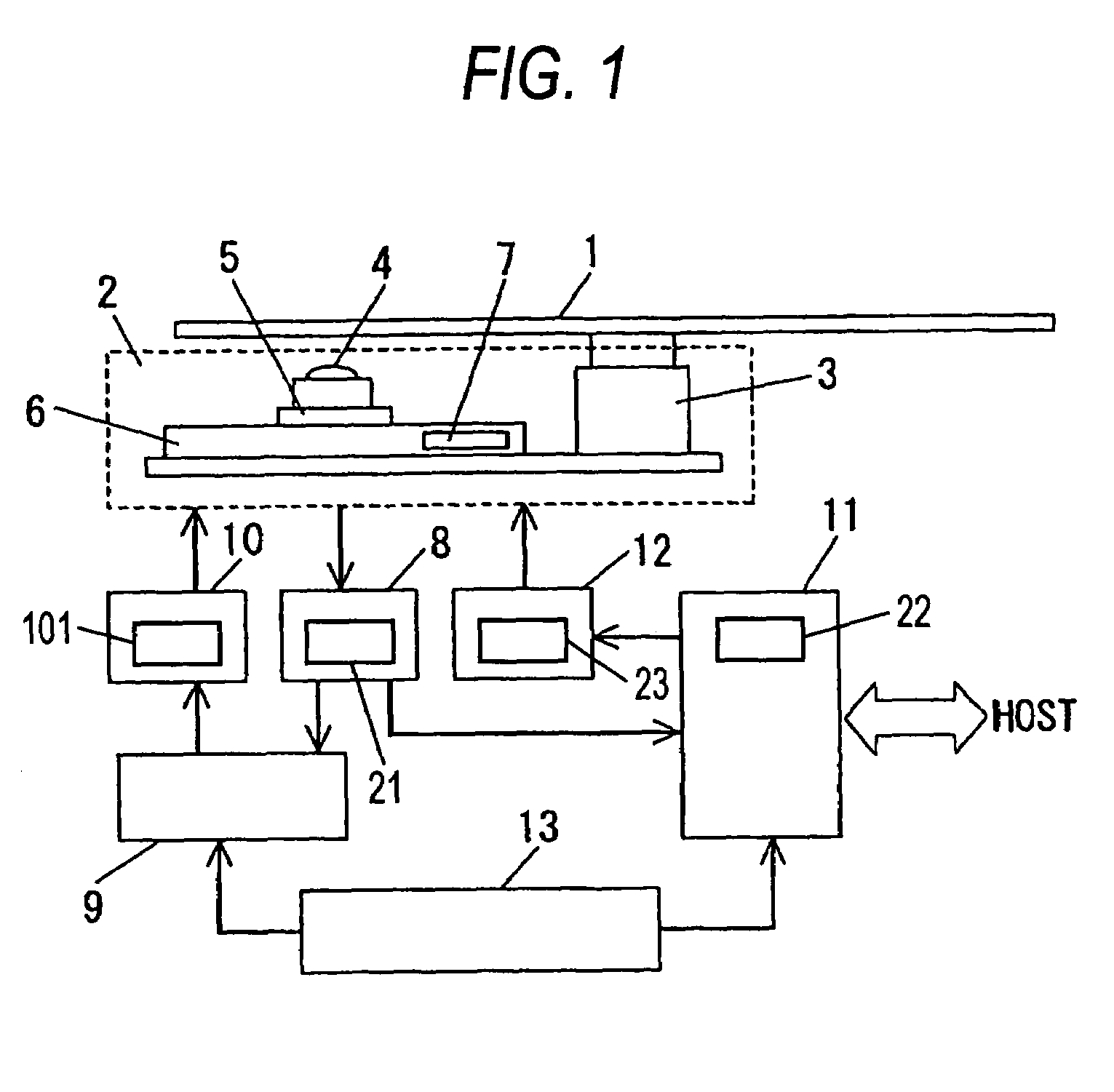
[0030]Operations of the pickup control part in this example are described. In FIG. 1, the pickup module 2 comprises a spindle motor 3 for rotating an optical disk 1, an optical pickup 4 for reading data signals of the optical disk 1, and a feed part 6 for moving a carriage 5 on which the optical pickup 4 is mounted in the radius direction of the optical disk 1. The feed part 6 comprises a feed motor 7, a gear (not shown), a screw shaft (not shown), etc., and is constructed so that the carriage 5 moves between the inner circumference and the outer circumference of the optical disk 1 by rotating the feed motor 7.

[0031]On the basis of signal outputs from an optical sensor ...


PUM

PropertyMeasurementUnit
emission currentaaaaaaaaaa
currentaaaaaaaaaa
erase currentaaaaaaaaaa

Abstract

A ratio of an erase current and a peak current when starting recording is defined as K=iER / iPK (S1), and iER11 is set equal to K×iPK1, and an ideal value iER11 of an erase current that should be increased according to a temperature change is determined (S2). A value obtained by subtracting a current iBT at a bottom level emission intensity when starting recording from a current at an erase level emission intensity after the temperature rises is defined as iER1. By measuring this iER1, an ideal value iER11 of the erase current is subtracted from iER1, and the resultant current is defined as iBT11 (S3). This iBT11 is set as an adjustment value of the bottom current, and a value obtained by adding this adjustment value to a bottom current when starting recording is set as a bottom current after change.

Description

BACKGROUND OF THE INVENTION[0001]The present invention relates to an optical disk device for recording and reproducing data on and from an optical disk by an optical pickup, and a method for adjusting an emission current of a laser in an optical disk device.[0002]As optical disk devices, devices for CD-ROMs, CD-R / RWs, and DVDs have already been made practicable, and these are actively applied to various fields and developed for higher performance. Particularly, recently, along with rapid market expansion of personal computers, the diffusion ratio thereof in the form installed in personal computers has also increased.[0003]FIG. 10 is a block diagram of a pickup control part of an optical disk device.[0004]Operations of a pickup control part according to prior arts are described with reference to FIG. 10. In FIG. 10, the pickup module 2 comprises a spindle motor 3 for rotating an optical disk 1, an optical pickup 4 for recording and reproducing data signals of the optical disk 1, and ...

Claims


Application Information

Patent Timeline
Patent Type & Authority Patents(United States)
IPC IPC(8): G11B7/00G11B7/0045G11B7/125G11B7/1263
CPCG11B7/1263G11B7/00456
Inventor ISHIBASHI, EISUKEWADA, YASUHIROSHIMIZU, SHINYAAKAGI, TOSHIYA
Owner PANASONIC CORP
Why Eureka
Try Eureka