Magnetically attracted apparatus, system, and method for remote bondline thickness measurement

a technology of magnetization and attachment apparatus, applied in the direction of instruments, specific gravity measurement, and analysis of solids using sonic/ultrasonic/infrasonic waves, etc., can solve the problems of easy damage to the joint, difficult or impossible access to interior surfaces and bondlines, and non-destructive ultrasoni

Inactive Publication Date: 2008-01-01
THE BOEING CO
View PDF29 Cites 17 Cited by
  • Summary
  • Abstract
  • Description
  • Claims
  • Application Information

AI Technical Summary

Benefits of technology

[0012]Improved apparatus, systems, and methods for inspecting a structure, such as a composite sandwich structure and particularly for measuring a remote bondline thickness, are provided which use magnetically coupled probes to locate, position, and support an ultrasonic transducer for non-destructive inspection. The present invention allows a technician to locate, move, and accurately position, a pulse echo ultrasonic sensor for measuring a remote bondline thickness.
[0017]To facilitate the coupling of the ultrasonic signal between the pulse echo ultrasonic sensor of the tracking probe and the structure, a couplant may be disposed between the sensor and the respective surface of the structure. A tracking probe of one advantageous embodiment includes fluid ports for pumping a fluid, typically water, into channels for evenly distributing the fluid between the sensor and the structure. In this regard, the tracking probe may include a housing in which the magnet and the pulse echo ultrasonic sensor are disposed. The channels may be, for example, a series of radially directed recesses or a plurality of holes. Where the channels include radially directed recesses, the channels may also include a ring shaped recess for evenly distributing fluid around the radially directed recesses.

Problems solved by technology

For example, if the bondline is too thick, the joint can be weakened.
However, access to interior surfaces and bondlines is often difficult or impossible without disassembly or damage to the structure, such as removing a part or drilling a hole into a structure for insertion of a measurement tool.
However, as mentioned above, many bonded joints are located on the interior of a product where the bondline may be inaccessible for inspection.
Non-destructive ultrasonic testing often involves coupling an ultrasonic signal from a transducer or transducer array to the surface of the structure under inspection, such as bubbling water between an inspection device and the structure.
More particularly, a technician's ability to perform inspection often is limited by the access the technician has to a location for placing a pulse echo ultrasonic sensor, such as at a remotely located internal surface position.
For example, access to a remote bondline (a bondline located in a remote position) may be so limited or inaccessible that a manual inspection by a technician is not possible or would require damage to the structure.
Alignment and positioning of sensors such as, pulse echo ultrasonic transducers and devices therefor, is similarly complicated by accessibility to the structure such as inaccessibility to one side of a composite sandwich structure.

Method used


Image

  • Magnetically attracted apparatus, system, and method for remote bondline thickness measurement
  • Magnetically attracted apparatus, system, and method for remote bondline thickness measurement
  • Magnetically attracted apparatus, system, and method for remote bondline thickness measurement

Examples


Embodiment Construction

[0033]The present invention will be described more fully with reference to the accompanying drawings. Some, but not all, embodiments of the invention are shown. The invention may be embodied in many different forms and should not be construed as limited to the embodiments described. Like numbers and variables refer to like elements and parameters throughout the drawings.

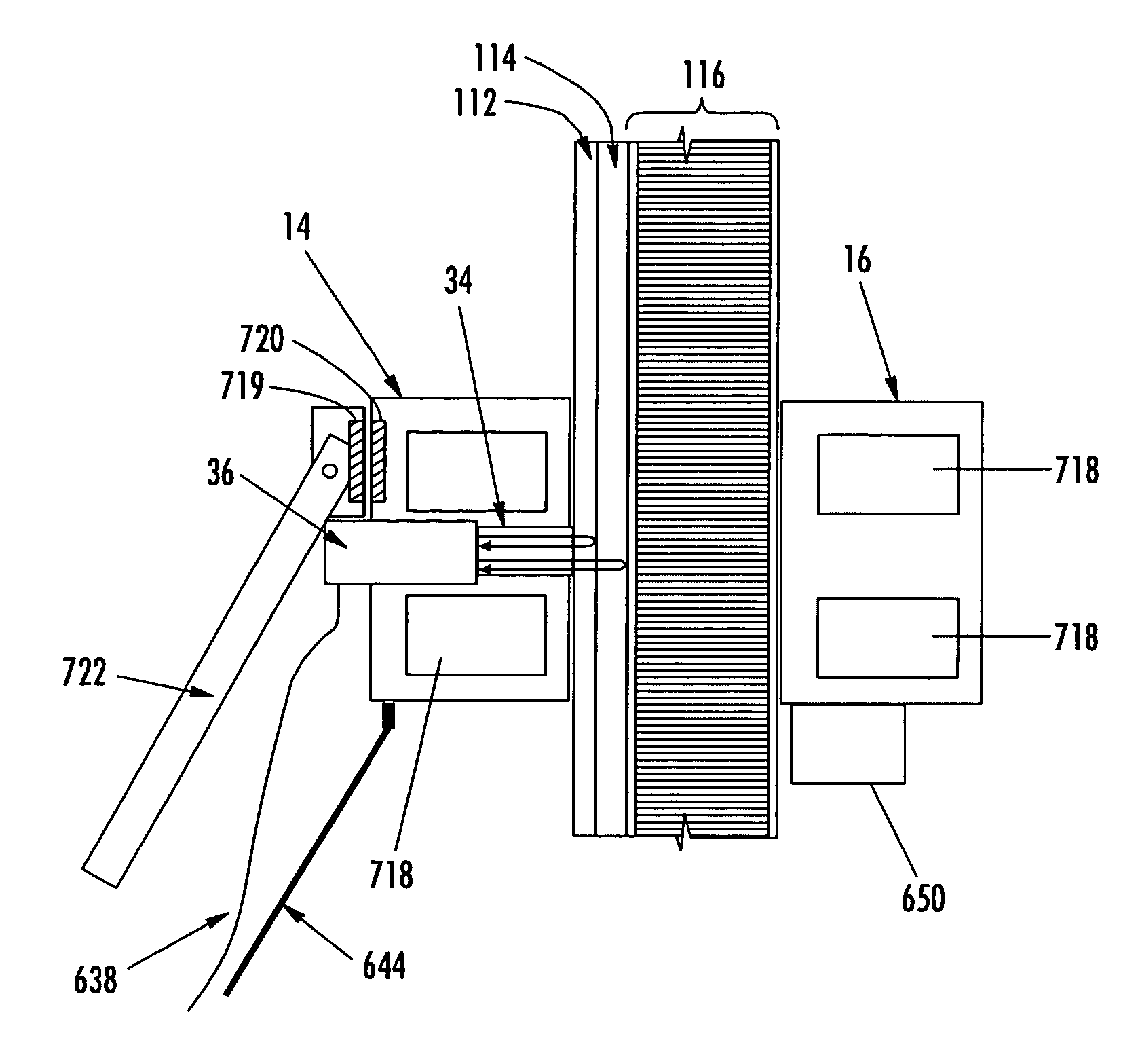
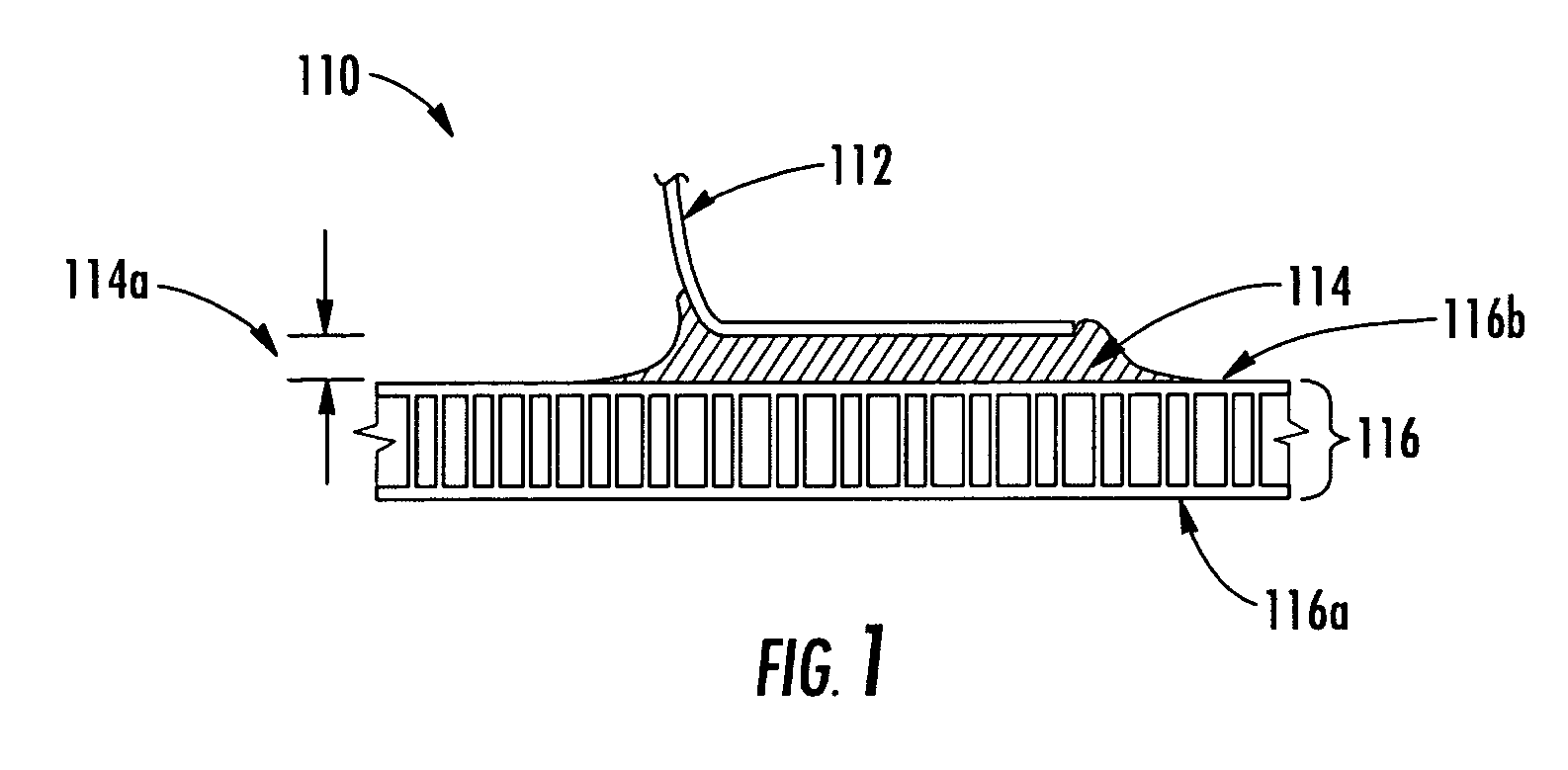
[0034]FIG. 1 is a schematic diagram of a composite sandwich structure 116 with an adhesive paste bond joint to a second composite structure 112, such as a bonded stiffener the thickness of which can be measured in accordance with the present invention. The composite sandwich structure 116 includes a honeycomb core layer which prevents measurement of the thickness of the bondline 114a using a pulse echo ultrasonic inspection method from the exterior side 116a of the composite sandwich structure. Rather, the thickness of the bondline 114a may be measured using pulse echo ultrasonic inspection from the unbonded side 112...


PUM

PropertyMeasurementUnit
bondline thicknessaaaaaaaaaa
thicknessaaaaaaaaaa
shapeaaaaaaaaaa

Abstract

Apparatus, systems, and methods for inspecting a structure are provided which use magnetically coupled probes disposed proximate opposite surfaces of a structure to locate, move, position, and hold a pulse echo ultrasonic transducer of one of the probes for non-destructive inspection, such as measuring a remote bondline thickness of a joint of a composite sandwich structure. The pulse echo ultrasonic sensor is included in a tracking probe, and the position of the tracking probe and pulse echo ultrasonic sensor are controlled by movement and positioning of a magnetically coupled driven probe in a leader-follower configuration. The tracking probe may be initially placed in a remote location using a detachable, and possibly deformable, placement rod.

Description

CROSS-REFERENCE TO RELATED APPLICATIONS[0001]The contents of U.S. Pat. No. 6,722,202 to Kennedy; application Ser. No. 10 / 752,890, entitled “Non-Destructive Inspection Device for Inspection Limited-Access Features of a Structure,” filed Jan. 7, 2004; application Ser. No. 10 / 943,088, entitled “Magnetically Attracted Inspecting Apparatus and Method Using a Ball Bearing,” filed Sep. 16, 2004; application Ser. No. 10 / 943,135, entitled “Magnetically Attracted Inspecting Apparatus and Method Using a Fluid Bearing,” filed Sep. 16, 2004; and application Ser. No. 10 / 943,170, entitled “Alignment Compensator for Magnetically Attracted Inspecting Apparatus and Method,” filed Sep. 16, 2004, are incorporated herein by reference in their entireties.FIELD OF THE INVENTION[0002]The present invention relates generally to an apparatus and method for inspecting a structure and, more particularly, to an apparatus, system, and method for measuring remote bondline thickness using a pair of magnetically cou...

Claims


Application Information

Patent Timeline
Patent Type & Authority Patents(United States)
IPC IPC(8): G01N29/24
CPCG01B17/02G01N29/043G01N2291/0231G01N2291/02854G01N2291/0422G01N2291/048G01N2291/102
Inventor GEORGESON, GARY E.FOGARTY, MICHAEL
Owner THE BOEING CO
Why Eureka
Try Eureka