Method of controlling operation of a liquid-fuel combustion appliance

a technology of liquid fuel combustion and control device, which is applied in the direction of positive displacement liquid engine, machine/engine, service pipe system, etc., can solve the problems of fuel remaining trapped inside the cavity, and affecting the combustion efficiency of the combustion applian

Active Publication Date: 2008-01-01
RIELLO
View PDF10 Cites 5 Cited by
  • Summary
  • Abstract
  • Description
  • Claims
  • Application Information

AI Technical Summary

Benefits of technology

[0015]It is an object of the present invention, therefore, to provide a method of controlling operation of a liquid-fuel burner, whereby the fuel pump is operated periodically to prevent seizing of the pump caused by polymerization of the fuel.
[0026]The purpose of this mode, in fact, is to prevent an increase in the viscosity of the liquid fuel in the pump when the pump is idle.

Problems solved by technology

When the pump is idle, however, fuel remains trapped inside the cavities formed by the geometry of the gears.
In certain conditions, and if the pump remains idle for any length of time, the fluid film deposited inside the cavities undergoes oxidation and / or polymerization, thus resulting in alteration of its properties, in particular viscosity.
That is, the starting torque of the electric motor is no longer enough to overcome the breakaway friction torque produced by the high-viscosity fluid deposit.
One of the causes of the problem is the addition of vegetable fuel to the mineral fuel.
Vegetable fuel may comprise unsaturated polymer chains, which, in the presence of oxygen or during prolonged stoppages, may combine to form macromolecules, the relative flow properties of which are greatly inferior to those of non-oxidized fuel.

Method used


Image

  • Method of controlling operation of a liquid-fuel combustion appliance
  • Method of controlling operation of a liquid-fuel combustion appliance

Examples


Embodiment Construction

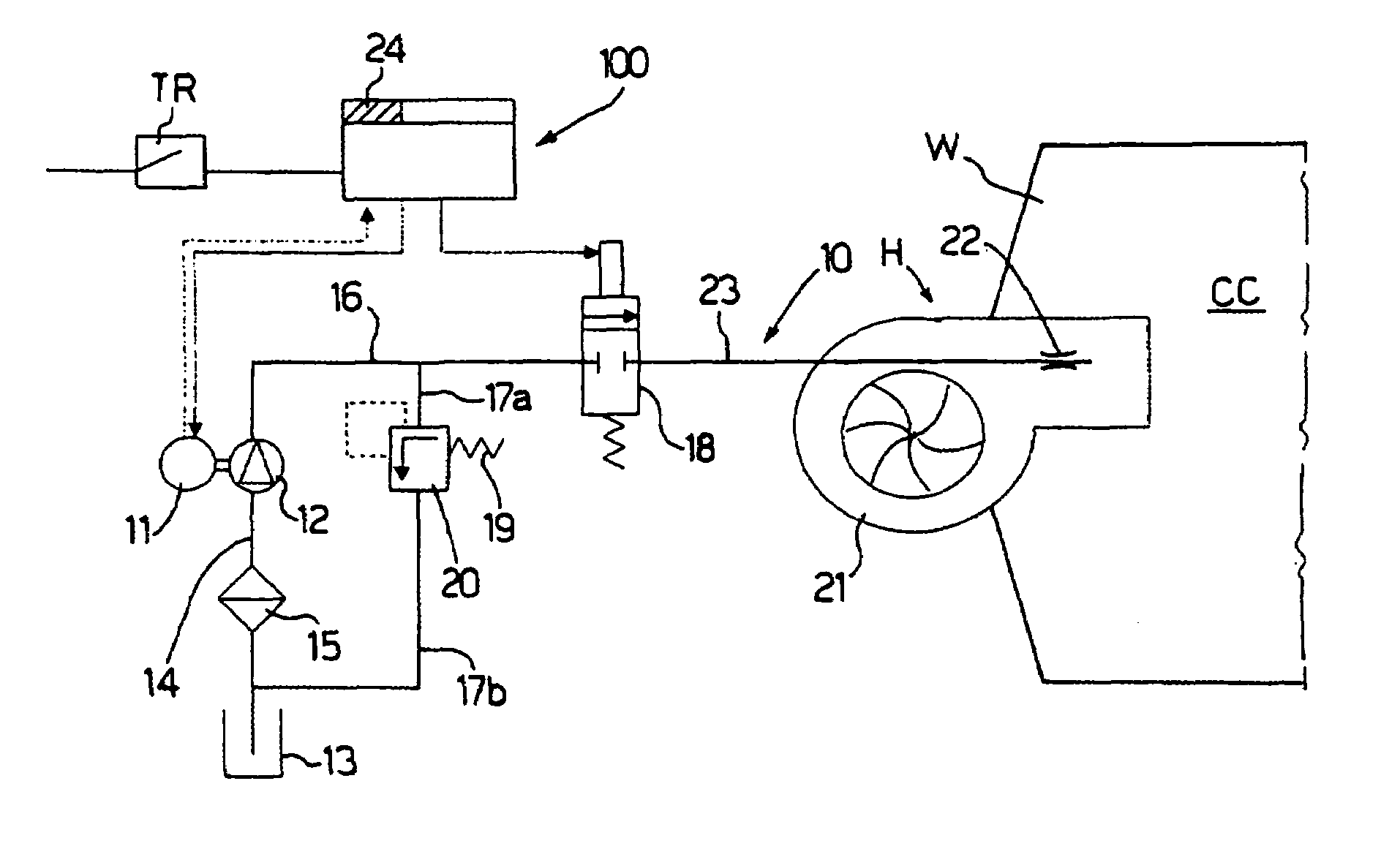
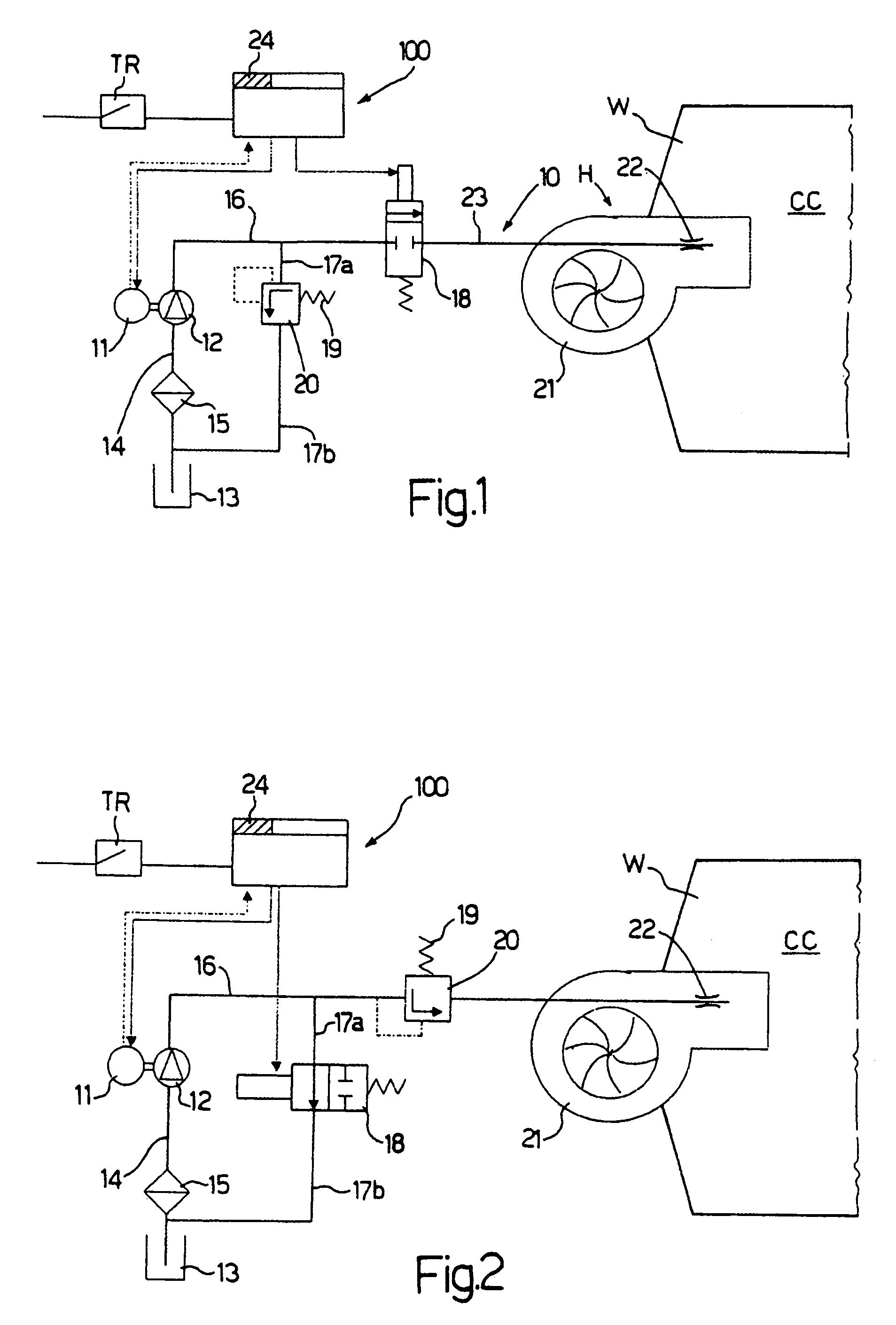
[0040]Number 10 in FIG. 1 indicates as a whole a combustion appliance for implementing the innovative method which is the main object of the present invention (see below).

[0041]In “standard operating mode”, heat demand by the outside environment closes a thermostat TR.

[0042]An electric signal is therefore sent to an electronic central control unit 100 for controlling all the operations performed by appliance 10.

[0043]Central control unit 100 controls operation of an electric motor 11 powering a gear pump 12.

[0044]Fuel is drawn by gear pump 12 from a tank 13 along an intake conduit 14 and via a filter 15.

[0045]The fuel then flows along a conduit 16 closed by a normally-closed valve 18, and along a conduit 17a.

[0046]When the fuel pressure reaches such a value as to activate a spring 19 of a regulating device 20 along conduit 17a, device 20 opens to drain the fuel into tank 13 along a conduit 17b.

[0047]For a few seconds, therefore, all the fuel pumped by pump 12 flows into tank 13 vi...


PUM


Abstract

A method of controlling operation of a liquid-fuel combustion appliance. The method is characterized by including an “antiseize operating mode” in which an electric motor and a fuel pump, powered by the electric motor, are started periodically to prevent oxidation and / or polymerization of the liquid fuel in the fuel pump when the fuel pump is idle. More specifically, the fuel pump is a gear pump.

Description

[0001]The present invention relates to a method of controlling operation of a liquid-fuel combustion appliance.BACKGROUND OF THE INVENTION[0002]Combustion appliances are known comprising at least one pump for feeding liquid fuel to at least one liquid-fuel atomizing head.[0003]More specifically, burners or heating units have at least one pump for drawing fuel from a tank and feeding it under pressure to at least one nozzle where the liquid is atomized and made suitable for combustion (mechanical atomization).[0004]Given the high pressures (5-20 bars) and low flow rates involved, the pumps are normally volumetric types.[0005]Gear-type volumetric pumps are the most commonly used.[0006]In pumps of this sort, one gear is driven by an electric motor, and in turn drives an idle second gear; and the liquid flows through an intake port into one of the cavities formed by the teeth of the two gears, and is discharged to the delivery port while gradually increasing in pressure.[0007]The two ge...

Claims


Application Information

Patent Timeline
Patent Type & Authority Patents(United States)
IPC IPC(8): F02M37/04F04B49/00
CPCF23K5/04F23K5/16
Inventor TONIATO, GIUSEPPE
Owner RIELLO
Why Eureka
Try Eureka