Hydrogen supply method

Inactive Publication Date: 2008-01-01
HONDA MOTOR CO LTD
View PDF20 Cites 13 Cited by
  • Summary
  • Abstract
  • Description
  • Claims
  • Application Information

AI Technical Summary

Benefits of technology

[0010]The present invention takes as its object the provision of a hydrogen supply method which can overcome such problems as described above and can reduce, by use of an inexpensive and compact

Problems solved by technology

On the other hand, hydrogen absorbing alloys are expensive so that if every hydrogen supply station i

Method used


Image

  • Hydrogen supply method
  • Hydrogen supply method
  • Hydrogen supply method

Examples


first embodiment

[0023]First of all, description will be made on the hydrogen supply method of the present invention.

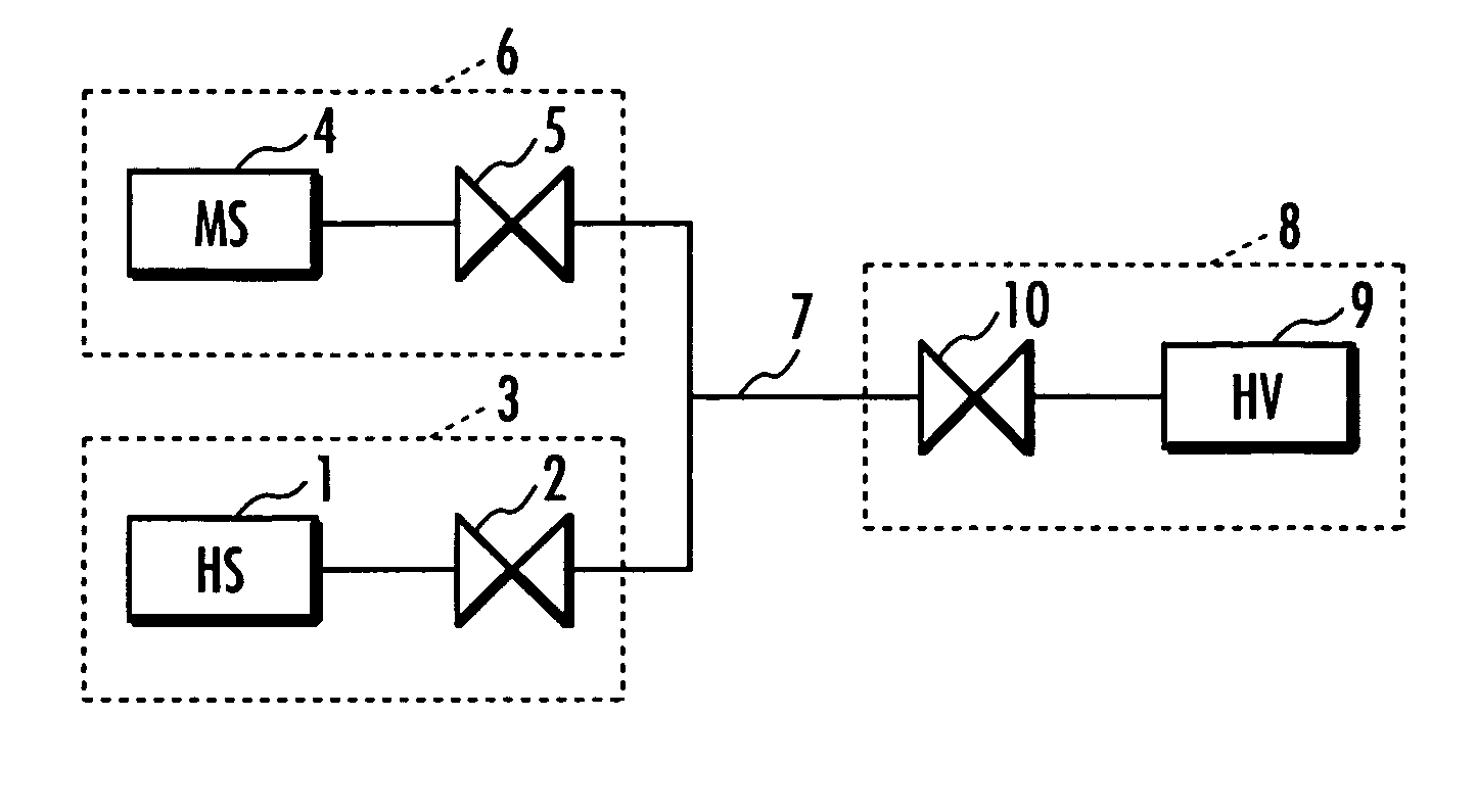
[0024]The hydrogen supply station used in the present embodiment comprises, for example as shown in FIG. 1, a first hydrogen supply means 3 comprising an in-station high pressure hydrogen tank HS 1 and an on-off valve 2 and a second hydrogen supply means 6 comprising a tank MS 4 containing a hydrogen absorbing alloy and an on-off valve 5. Thus, the method of the present embodiment supplies hydrogen by connecting through a hydrogen duct 7 the first hydrogen supply means 3 and the second hydrogen supply means 6 to an in-fuel-cell-vehicle high pressure hydrogen tank HV 9 mounted on a fuel cell vehicle 8. The tank HV 9 has a hydrogen storage capacity of 36.3 Nm3 and a maximum filling pressure of 35 MPa, and comprises an on-off valve 10.

[0025]In order to supply hydrogen to the tank HV 9 having the above described maximum filling pressure, the tank HS 1 used is the one which has a hydrogen ...

second embodiment

[0031]Then, description will be made below on the present invention.

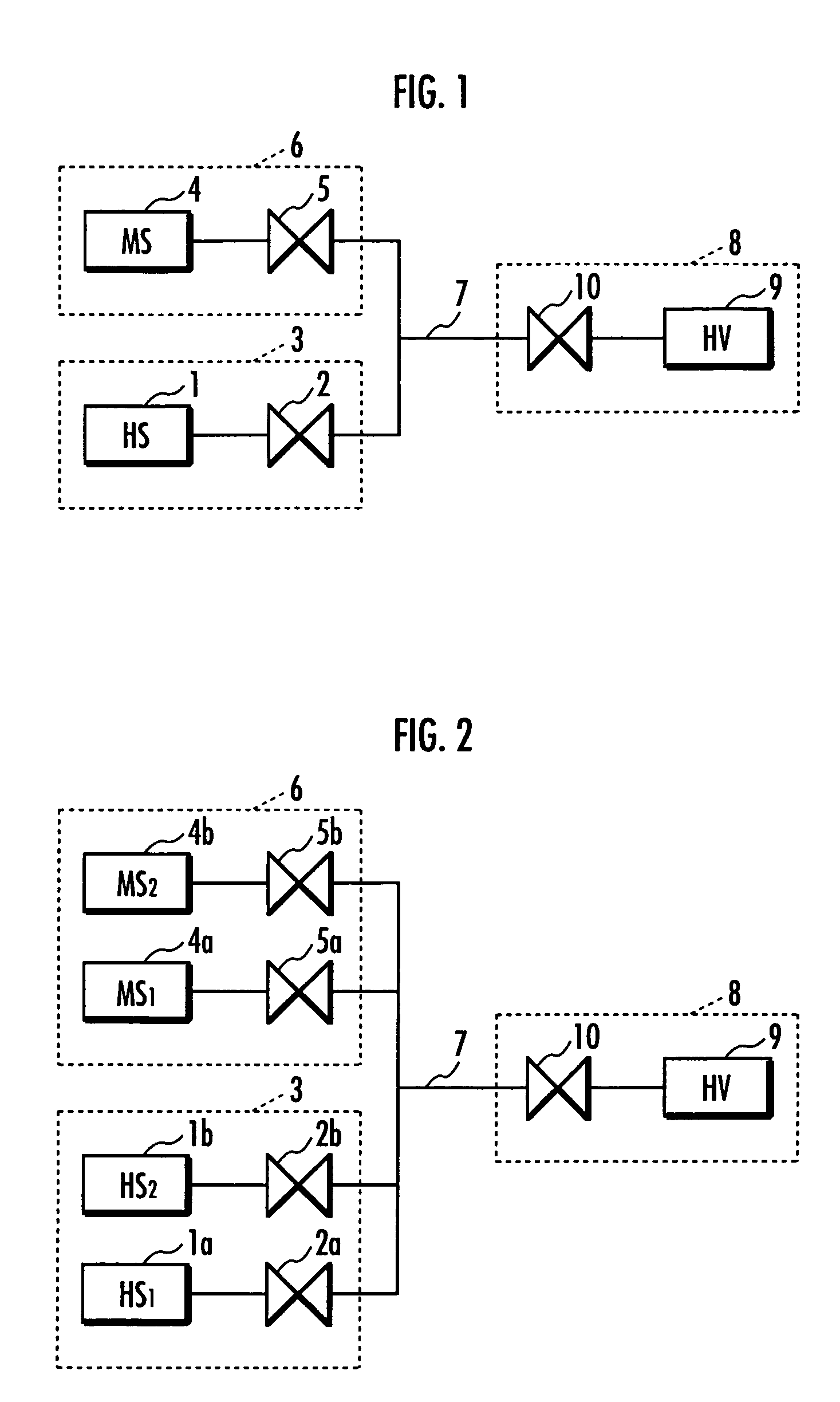
[0032]In the hydrogen supply station used in the present embodiment, a first hydrogen supply means 3 comprises, for example as FIG. 2 shows, two in-station high pressure hydrogen tanks HS1 1a and HS2 1b and on-off valves 2a and 2b respectively equipped for the tanks HS1 1a and HS2 1b. The tank HS1 1a has a hydrogen storage capacity of 13.4 Nm3 and an initial hydrogen pressure of 35 MPa, while the tank HS2 1b also has a hydrogen storage capacity of 13.4 Nm3 and an initial hydrogen pressure of 35 MPa. The tanks HS1 1a and HS2 1b each has an outside volume of 46 liters.

[0033]On the other hand, a second hydrogen supply means 6 comprises two tanks MS1 4a and MS2 4b containing a hydrogen absorbing alloy and on-off valves 5a and 5b respectively equipped for the tanks MS1 4a and MS2 4b. The tank MS1 4a has a hydrogen storage capacity of 9 Nm3 and contains a hydrogen absorbing alloy having a hydrogen release pressure of 24.1...


PUM

PropertyMeasurementUnit
Pressureaaaaaaaaaa
Pressureaaaaaaaaaa
Compositionaaaaaaaaaa

Abstract

A hydrogen supply method using an inexpensive and compact hydrogen supply means to reduce a pressure of hydrogen stored in the hydrogen supply means and to supply efficiently hydrogen to a high pressure hydrogen storage means. Hydrogen is supplied under high pressure from first hydrogen supply means and from second hydrogen supply means containing a hydrogen absorbing alloy to a hydrogen storage means for storing hydrogen under high pressure. Hydrogen is supplied from the first hydrogen supply means to the hydrogen storage means until the pressure in the hydrogen storage means reaches a predetermined pressure. Thereafter, hydrogen is supplied from the second hydrogen supply means to the hydrogen storage means until the pressure in the hydrogen storage means reaches a maximum filling pressure. A plurality of the first hydrogen supply means or a plurality of the second hydrogen supply means may be used.

Description

BACKGROUND OF THE INVENTION[0001]1. Field of the Invention[0002]The present invention relates to a method for supplying hydrogen, for example, to high pressure hydrogen tanks mounted on vehicles and the like which use fuel cells.[0003]2. Description of the Related Art[0004]In these years, it has been investigated to use fuel cells as power source for vehicles and the like. In an above described vehicle which uses a fuel cell (hereinafter abbreviated as a fuel cell vehicle), a high pressure hydrogen tank is mounted on the vehicle for storing hydrogen used as fuel for the fuel cell.[0005]Conventionally, rapid filling methods have been known as the method for supplying hydrogen to a high pressure hydrogen tank mounted on a fuel cell vehicle (see, for example, Japanese Patent Laid-Open No. 2002-89793).[0006]As FIG. 4 shows, the above described rapid-filing method supplies hydrogen from a hydrogen supply means 3, comprising an in-station high pressure hydrogen tank HS 1 installed at a st...

Claims


Application Information

Patent Timeline
IPC IPC(8): F17D1/00C01B3/00F16K31/163H01M8/04
CPCF16K31/1635H01M8/04201Y02E60/50Y02E60/34Y02E60/327Y02E60/32Y10T137/0352Y10T137/0396Y10T137/4673
Inventor YAMASHITA, IKUYAKOMURA, NORIO
Owner HONDA MOTOR CO LTD
Why Eureka
Try Eureka