
System for biometric security using a smartcard

a biometric security and smartcard technology, applied in the field of biometric security using a smartcard, can solve the problems of insufficient authentication of transactions, inability to properly address the authentication issues of transactions, and inability to use biometric security in association with smartcards. modern traveler may be often subject to unnecessary delays, petty inconveniences, and oppressive paperwork

Inactive Publication Date: 2008-01-01
LIBERTY PEAK VENTURES LLC
View PDF360 Cites 142 Cited by
  • Summary
  • Abstract
  • Description
  • Claims
  • Application Information

AI Technical Summary

Benefits of technology

[0007]The present invention may provide methods and apparatus for a smartcard system which securely and conveniently integrates important travel-related applications with biometric security, thereby overcoming the limitations of the prior art. In accordance with one aspect of the present invention, a smartcard system may comprise a cardholder identification application and various additional applications useful in particular travel contexts; for example, airline, hotel, rental car, and payment-related applications. In accordance with another aspect of the present invention, a smartcard system further may comprise space and security features within specific applications which provide partnering organizations the ability to construct custom and secure file structures.

Problems solved by technology

While some smartcard systems have streamlined the transaction process and provided a system for managing more information, smartcard technology has still not adequately addressed some of the authentication issues related to transactions.
Moreover, while biometric technology exists with respect to certain access systems and limited financial systems, the use of biometric security in association with smartcards remains underdeveloped and scarce.
Additionally, despite advances in information technology and process streamlining with respect to travel arrangements, the modern traveler may be often subjected to unnecessary delays, petty inconveniences, and oppressive paperwork.
These travel burdens may be most evident in the airline, hotel, and rental car industries, where arranging and paying for services and accommodations may involve significant time delays due to miscommunication, poor record-keeping, and a host of other administrative inefficiencies.

Method used


Image

  • System for biometric security using a smartcard
  • System for biometric security using a smartcard
  • System for biometric security using a smartcard

Examples


Embodiment Construction

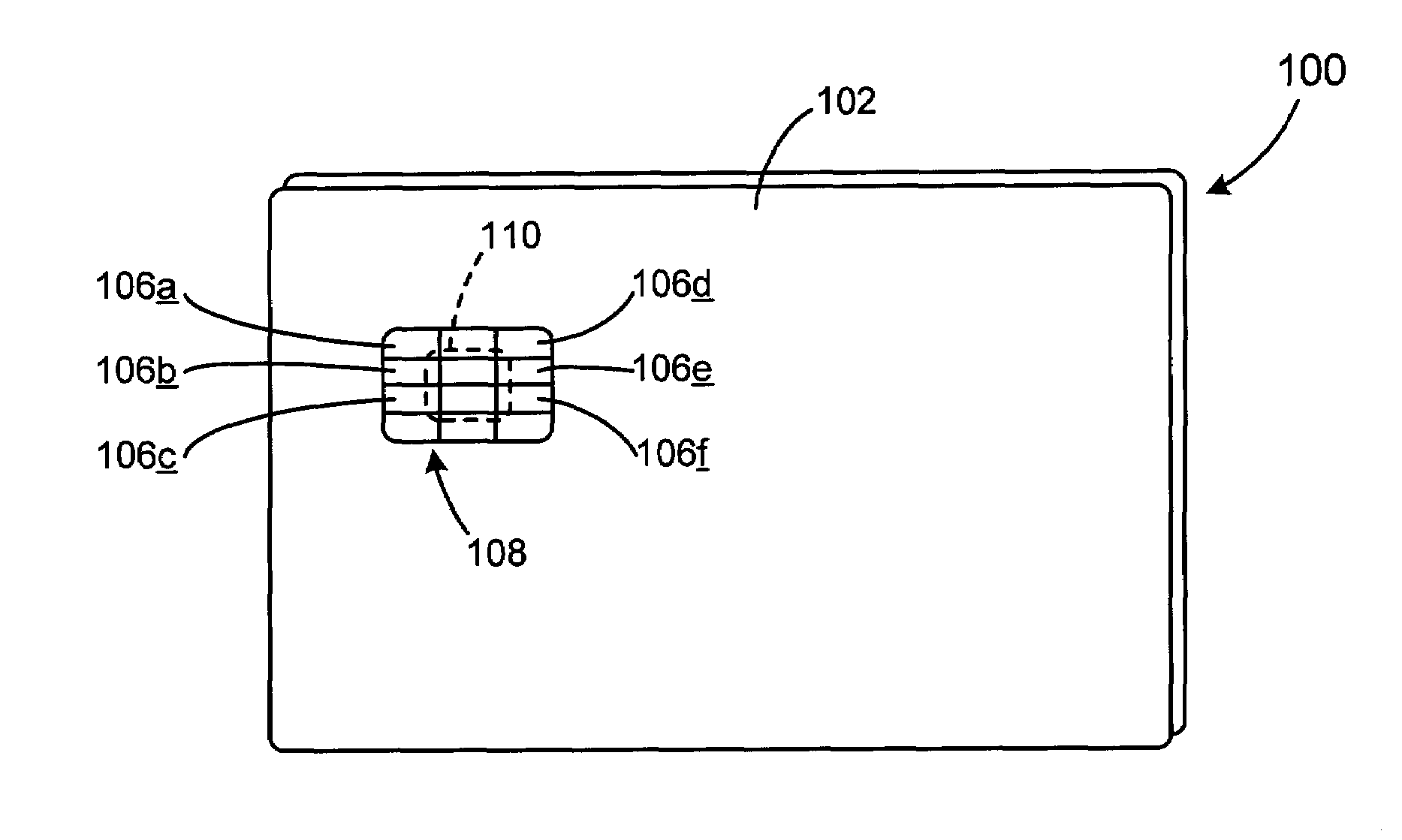
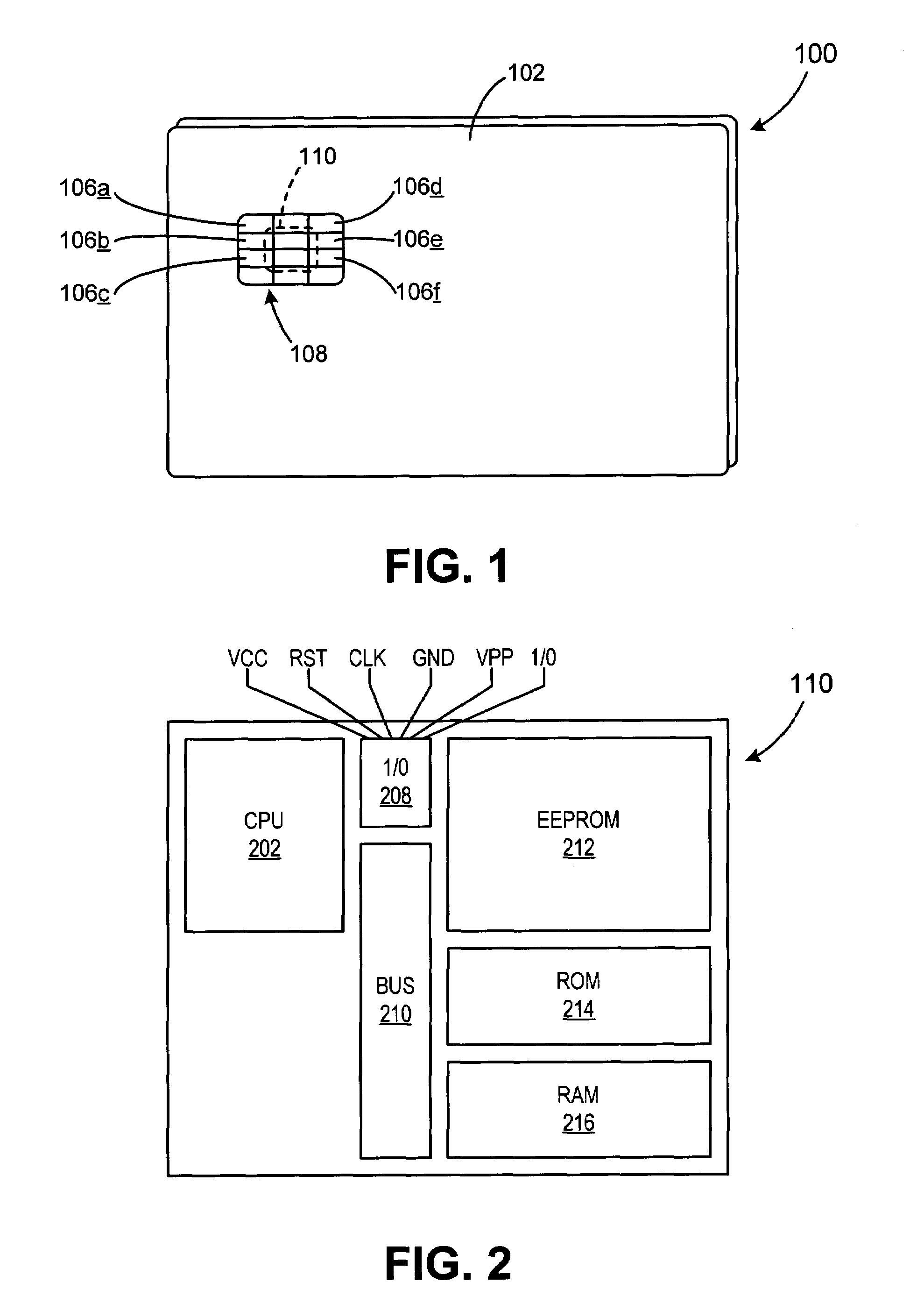
[0039]Referring now to FIGS. 1 and 2, an exemplary smartcard system suitable for practicing the present invention may now be described. A smartcard 100 generally may comprise a card body 102 having a communication region 108 for providing contact or non-contact communication between an external device (e.g., a card reader) and an integrated circuit 110 encapsulated within card body 102. Communication region 108 preferably may comprise six conductive pads 106 whose placement and size conform to ISO-7816-2. More particularly, a communication region 108 in conformance with ISO-7816-2 preferably may comprise VCC contact 106(a) (power supply), RST contact 106(b) (reset), CLK contact 106(c) (external clock), GND Contact 106(d) (ground), VPP contact 106(e) (programming voltage), and I / O contact 106(f) (data line).

[0040]VCC 106(a) may suitably provide power to IC 110 (typically 5.0 V+ / −10%). CLK 106(c) may be suitably used to provide an external clock source which acts as a data transmissio...


PUM


Abstract

The present invention discloses a system and methods for biometric security using biometrics in a smartcard-reader system. The biometric security system also includes a biometric sensor that detects biometric samples and a device for verifying biometric samples. In one embodiment, the biometric security system includes a smartcard configured with a biometric sensor. In another embodiment, the system includes a reader configured with a biometric sensor. The device for verifying samples compares the biometric samples with information stored on databases.

Description

FIELD OF INVENTION[0001]The present invention relates generally to the use of integrated circuit cards, or “smartcards,” for commercial transactions and, more particularly, to methods and system for using biometrics with a smartcard in the context of a distributed transaction system.BACKGROUND OF INVENTION[0002]The term “smartcard” refers generally to wallet-sized or smaller cards incorporating a microprocessor or micro-controller to store and manage data within the card. More complex than magnetic-stripe and stored-value cards, smartcards may be characterized by sophisticated memory management and security features. A typical smartcard may include a microcontroller embedded within the card plastic which may be electrically connected to an array of external contacts provided on the card exterior. A smartcard microcontroller generally may include an electrically-erasable and programmable read only memory (EEPROM) for storing user data, random access memory (RAM) for scratch storage, ...

Claims


Application Information

Patent Timeline
Patent Type & Authority Patents(United States)
IPC IPC(8): G06K5/00G06K19/00G06K19/06G08B13/14H04Q5/22
CPCG07C9/00103G07F7/1008G06Q20/341G06Q20/3674G06Q20/40145G07C9/00087G07C2009/00095G07C9/26G07C9/257G07C9/27
Inventor BONALLE, DAVID S.SALOW, GLEN
Owner LIBERTY PEAK VENTURES LLC
Learn More