
Security device and transponder

a transponder and security technology, applied in the direction of burglar alarms, mechanical actuation of burglar alarms, instruments, etc., can solve the problems of normal operation of conventional transponders based on magnetic dipoles, frequency shift of signals, and difficulty in mounting them in a position when used with containers, so as to reduce the generation of eddy currents in the electrically conductive layer by the transponder, reduce the effect of eddy current generation and narrow width

Inactive Publication Date: 2008-01-01
DUBOIS LIMITED (GB)
View PDF17 Cites 29 Cited by
  • Summary
  • Abstract
  • Description
  • Claims
  • Application Information

AI Technical Summary

Benefits of technology

[0021]As mentioned above, the transponder according to the present invention is in the form of a substantially flat strip whose magnetic dipole preferably lies substantially along at least part of the length thereof. Consequently, an advantage of the present invention is that by orienting the security device such that the magnetic dipole of its transponder lies approximately parallel to the electrically conductive layer or region, the attenuation of the magnetic moment generated by the transponder may be insufficient to disrupt the correct functioning of the transponder. This is because, by orienting the transponder such that its magnetic dipole is approximately parallel to the electrically conductive layer or region, the eddy currents generated by the transponder in the electrically conductive layer or region may be minimised. This is explained further below.
[0022]A sixth aspect of a preferred embodiment of the invention provides a kit of parts comprising an apparatus for holding one or more articles, and a security device according to the third aspect of a preferred embodiment of the invention adapted to be secured thereto.
[0023]Preferably the kit is arranged such that when the security device is secured to the apparatus, the magnetic dipole generated in use by the transponder is oriented substantially parallel to an electrically conductive layer or region of an article held by the apparatus. Advantageously, for those embodiments of the invention in which the article is a media storage disk (e.g. a CD or a DVD), the longitudinal centre of the axis of the magnetic dipole generated by the transponder preferably is adjacent to a window in the electrically conductive layer of the disk (e.g. a window around the central hole provided in the disk). In this way, the generation of eddy currents in the electrically conductive layer by the transponder may be minimised. Additionally or alternatively, the axis of the magnetic dipole generated by the transponder may extend between two such disks.
[0024]Advantageously, the kit may be arranged such that when the security device is secured to the apparatus, the transponder of the security device is adjacent to an external wall of the apparatus. Preferably the transponder of the security device is housed within the apparatus, e.g. adjacent to an external wall of the apparatus.
[0025]The flat strip of magnetic material of the transponder may, for example, have a simple rectangular shape. However, in at least some preferred embodiments of the invention, part of the length of the strip may have a narrower width than the remainder of the strip. For example, the strip may have an approximate H-shape. Advantageously, the elongate electrical conductor may be wound around only the narrower part of the strip.
[0026]The flat strip of magnetic material of the transponder preferably is a ferromagnetic material or a ferrimagnetic material. Preferred such materials include ferrites, especially a mixed oxide of iron and nickel and / or zinc and / or cobalt and / or manganese. Such materials generally comprise ceramics. Examples of two particularly preferred nickel-zinc ferrites, chosen by experimentation by the present inventors, are: F16 supplied by TT Electronics and 4C65 supplied by Philips.

Problems solved by technology

A problem that arises with some of these devices, particularly with electromagnetic devices such as RF tags, is that they can be shielded by a metal layer, e.g. the metal layer within a CD or DVD, yet it is desirable to be able to use this form of tag as a significant proportion of retail outlets use RF alarm systems rather than AM alarm systems.
Such shielding may attenuate electromagnetic signals passing therethrough and / or cause frequency shift of the signals.
RF tags comprising flat coils can be used but as they are relatively large it is difficult to mount them in a position when used with a container such as a CD or DVD box where they do not suffer from shielding.
This causes a problem in that the functioning of conventional transponders based upon magnetic dipoles normally is disrupted by the presence of such metal layers, because eddy currents generated in the metal layer by the magnetic dipole of the transponder cause attenuation of the magnetic moment generated by the transponder.
Thus, the magnetic field generated by the conventional transponder when the transponder is placed in the magnetic field of an alarm unit may be insufficient to trigger the alarm.
This is particularly the case, for example, when the strip is formed from a ferrite material, because such materials often tend to be brittle.

Method used


Image

  • Security device and transponder
  • Security device and transponder
  • Security device and transponder

Examples


Embodiment Construction

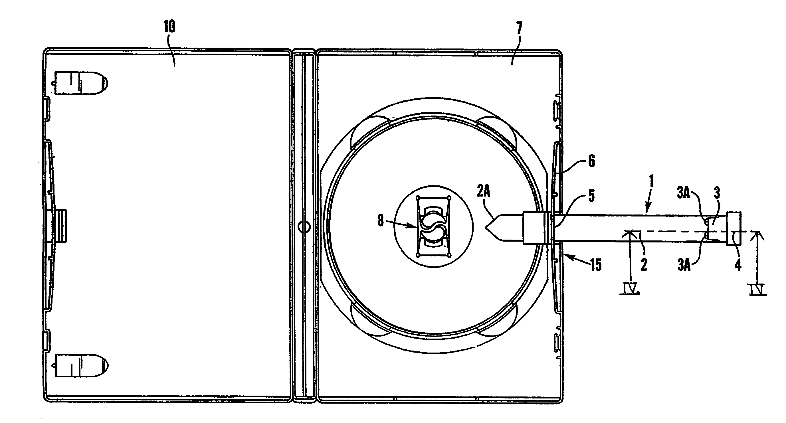
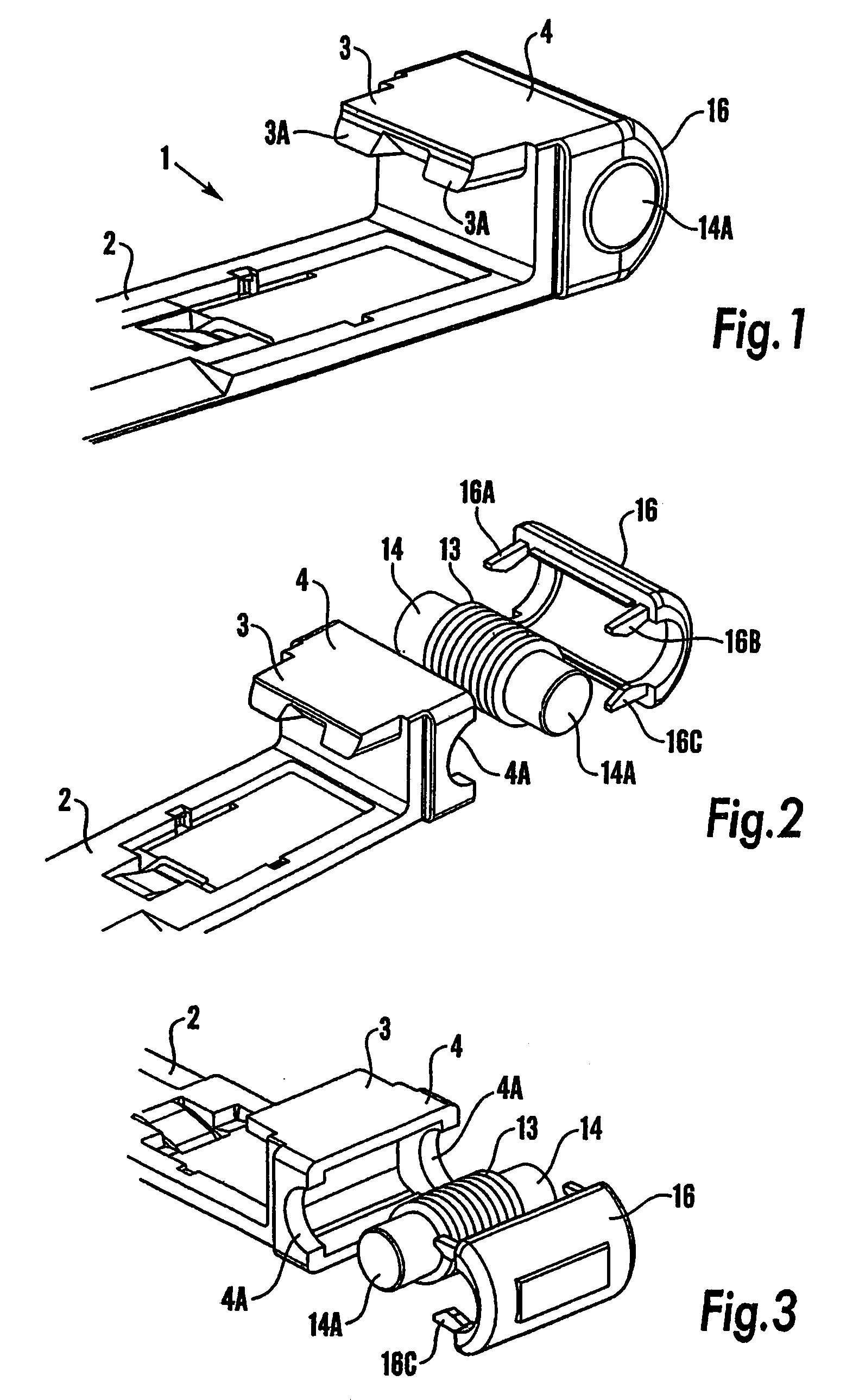
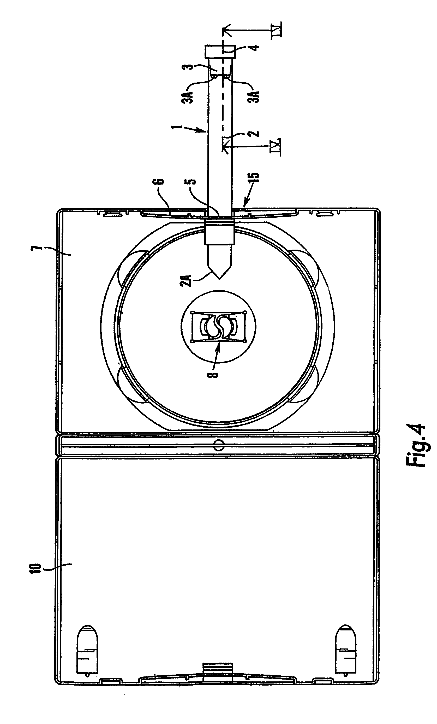
[0054]The embodiment of the security device illustrated in FIGS. 1-5 is designed for use with a CD or DVD container of the type described in WO 02 / 39451, the disclosure of which is incorporated herein. The security device may, however, be used with other types of container.

[0055]The security tag 1 shown in FIGS. 1-3 comprises a long arm 2 and a short arm 3 both arms projecting from a head portion 4. The long and short arm 2, 3 may be similar to those described in WO 02 / 39451. As shown in FIG. 4, the long arm 2 is designed to be inserted through an aperture or slot 5 in a side wall 6 of a base portion of a DVD container. Preferably, it extends across the base portion 7 and interacts with disk-holding means 8 on the base portion 7 to lock the disk (not shown) onto the base portion 7 as described in WO 02 / 39451. As shown in FIG. 5, the short arm 3 is designed to be inserted through an aperture or slot 9 in a side wall of a lid portion 10 of the container which is hingedly attached to t...


PUM


Abstract

A security device for attachment to a container having external walls such that a transponder thereon is located externally of or adjacent to one of said external walls so as to avoid being shielded by a metal layer within the container (e.g. the metal layer within a disk such as a CD or DVD). The security device is arranged to trigger an alarm signal if the container is moved within the range of an alarm unit with the security device attached thereto, and has a releasable locking mechanism to secure it to the container such that release of the locking mechanism requires the use of authorized release means. In one embodiments the transponder is located in the vicinity of a window in a metal layer, e.g. at the centre of the disk.

Description

CROSS REFERENCE TO RELATED APPLICATIONS[0001]This application is a continuation-in-part of prior International Application PCT / GB03 / 002885, filed Jul. 4, 2003, the entirety (including any amendments thereto) of which is incorporated herein by reference. This application also incorporates by reference in its entirety UK patent application GB-0420089.5, filed Sep. 10, 2004.TECHNICAL FIELD[0002]A preferred embodiment of the invention relates to a security device and / or a transponder for attachment to a container, for example to a container housing a disk such as a CD or DVD, to help in preventing or deterring its theft from a retail outlet.BACKGROUND ART[0003]It is well known to use security tags on retail items which trigger an alarm when the item is taken passed alarm units located at the exit of a store without prior removal of the security tag. These are known as Electronic Article Surveillance (EAS) labels or tags. There are 3 main types of devices: electromagnetic devices, acoust...

Claims


Application Information

Patent Timeline
IPC IPC(8): G08B21/00
CPCG08B13/2434
Inventor PIJANOWSKI, STEFAN A.FARRAR, PETER A.FRASER, ANTHONY H. J.JOHNSTON, ROBERTCROSSFIELD, MICHAEL D.JONES, ROSS P.
Owner DUBOIS LIMITED (GB)
Learn More