Display illumination system and manufacturing method thereof

a technology of illumination system and manufacturing method, which is applied in the direction of polarizing elements, lighting and heating apparatus, instruments, etc., can solve the problems of unwanted polarization of a substantial amount of light, and achieve the effect of increasing the amount of polarized light, reducing the formation of stray light, and smooth surfa

Inactive Publication Date: 2008-01-01
KONINK PHILIPS ELECTRONICS NV
View PDF16 Cites 18 Cited by
  • Summary
  • Abstract
  • Description
  • Claims
  • Application Information

AI Technical Summary

Benefits of technology

[0006]An advantage of the invention is that fibers with a very smooth surface are often easily available. The smooth surface of the fibers decreases the formation of stray light and increases the amount of polarized light that is deflected in the desired direction. The fibers are preferably such fibers that are available as staple commodities in e.g. the optical communications area or the fabric manufacturing area.
[0007]An other advantage of the invention is that the fibers make it easier to control the degree of birefringence by proper choice of type, material, shape and diameter of the fibers and to make those properties be the same for all individual fibers attached on the light guide. Thus it becomes much easier to provide an optical waveguide that provides the desired direction for the outcoupled polarized light.
[0008]In prior art optical waveguides the so called director function, i.e. the direction of orientation of the optical axis, of the birefringent material, i.e. the function that makes light of one polarization and incident from a certain direction see only one refractive index, either the ordinary or the extraordinary refractive index depending on the polarization, is not always well controlled. In prior art light of one polarization, e.g. s-light, may thus see both the ordinary and the extraordinary refractive index thus “wasting” some light that is thereby not outcoupled as desired. Further, still in the prior art, some light of the other polarization, e.g. p-light, also sees both the ordinary and the extraordinary refractive index and unintentionally becomes outcoupled to some degree. The invention provides an improved director function and outcouples all of, and almost only, the light of the desired polarization.
[0009]The measure according to claim 2 has the advantage of providing a still better control of the direction of the outcoupled polarized light.
[0010]The measure according to claim 3 has the advantage of providing an efficient way of providing fibers with birefringent properties. Fibers made of plastic polymer materials are easily available. By adjusting the degree of stretching the birefringent properties can be controlled with a high accuracy. By stretching the fibers it is ensured that the birefringent properties of the fibers are dependent on the direction of incident light. Light incident in a direction perpendicular to the stretched fibers, which have been longitudinally stretched, will see the two different refractive indexes, while light incident in the fibre direction will only see one refractive index, being the ordinary refractive index. The stretching of the fibers provides for an optimum director function in that light of a certain polarization, s-light or p-light, incident perpendicular to the stretched fibers will see only one refractive index. Thus the light of the desired polarization will become outcoupled to a very high degree while light of the unwanted polarization will hardly be outcoupled at all.
[0011]The measure according to claim 4 has the advantage of protecting the fibers from scratches and dirt that might deflect the polarized light in an unwanted direction. Further the resin layer assists in keeping the fibers in place on the light guide. Since the resin layer is isotropic it will not itself contribute to the polarization. This makes the polarization behaviour of the optical light guide easier to control.

Problems solved by technology

The optical wave guide is however sensitive to the manufacturing steps and may, if the grooves do not obtain a high quality with respect to surface properties and filling, result in the outcoupling of a substantial amount of light of the not wanted polarization.

Method used


Image

  • Display illumination system and manufacturing method thereof
  • Display illumination system and manufacturing method thereof
  • Display illumination system and manufacturing method thereof

Examples


Embodiment Construction

[0029]In the description below “birefringent” means that a transparent object has one refractive index, the ordinary refractive index, towards light of a first polarization and another refractive index, the extraordinary refractive index, towards light of a second polarization being opposite to said first polarization. Materials that show birefringence can be called “anisotropic”. A material that has the same refractive index regardless of the polarization of the light is called “isotropic”.

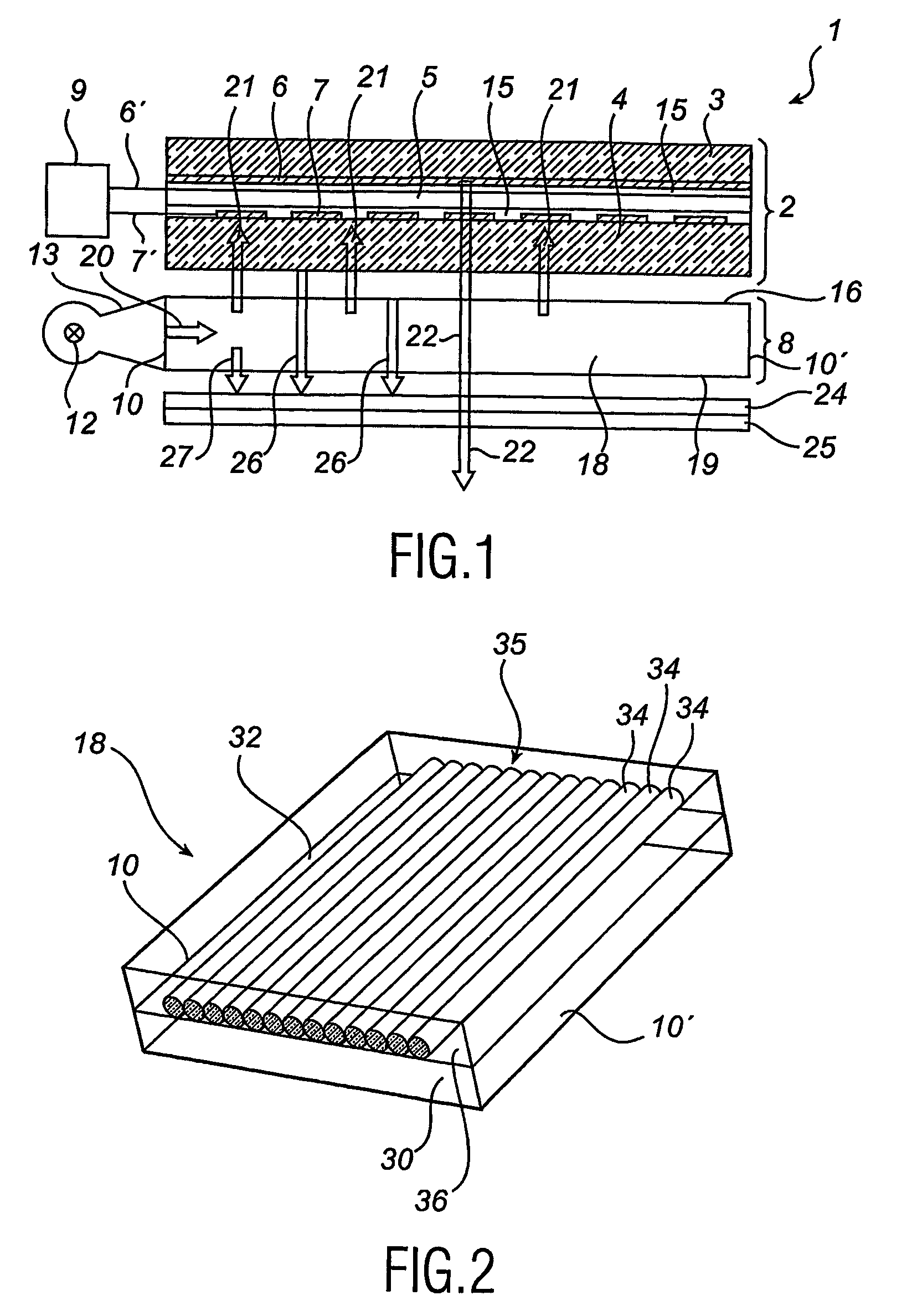
[0030]A display device 1 shown diagrammatically in FIG. 1 comprises an image display panel 2 and an illumination system 8 located between a not shown viewer and the display panel 2 and thus providing a front light illumination of the display panel 2.

[0031]The image display panel 2 comprises a liquid crystalline material 5 between two substrates 3, 4, based on the twisted nematic (TN), the supertwisted nematic (STN) or the ferroelectric effect so as to modulate the direction of polarization of inc...


PUM

PropertyMeasurementUnit
thicknessaaaaaaaaaa
thicknessaaaaaaaaaa
diameteraaaaaaaaaa

Abstract

An illumination system (8) comprises an optical waveguide (18) which is made from optically transparent components and has four end faces (10, 10′). A light source (12) whose light is coupled into the optical waveguide (18) via one of the end faces (10), is situated opposite this end face (10). The optical waveguide (18) has a light guide (30). A number of fibers (34) are attached to a surface (32) of the light guide (30). The fibers (34) have birefringent properties. A preferred method of providing the birefringent properties is to stretch fibers (34) of a suitable polymer plastic material in their longitudinal direction. The light from the light source (12) will be polarized by the fibers (34) and polarized light will be outcoupled from the optical waveguide (18) via an exit surface (16). The illumination system (8) may be used for front or back lightning of LCD panels for e.g. mobile phones, PDA's, etc.

Description

FIELD OF THE INVENTION[0001]The present invention relates to an illumination system comprising an optical waveguide being optically transparent and having an exit surface and a plurality of end faces, opposite to at least one of which a light source is situated, whose light is to be coupled in to the optical waveguide at said at least one end face, the optical waveguide having polarizing means integrated therein for polarizing the light emitted by the light source.[0002]The invention further relates to a method of manufacturing polarizing means in an optical waveguide being optically transparent and having an exit surface and a plurality of end faces, opposite to at least one of which a light source is adapted to be situated, whose light is to be coupled in to the optical waveguide at said at least one end face, the polarizing means being adapted to polarize the light emitted by the light source.BACKGROUND OF THE INVENTION[0003]LCD displays are frequently used for displaying informa...

Claims


Application Information

Patent Timeline
Patent Type & Authority Patents(United States)
IPC IPC(8): G02B6/02G02B6/10F21V8/00G02B5/30G02F1/13357G02F1/13363
CPCG02B5/3008G02B6/0056G02F1/13362G02F1/133615G02F2202/022G02F1/13363G02F2201/02G02F1/125
Inventor HUCK, HUBERTINA PETRONELLA MARIAHIKMET, RIFAT ATA MUSTAFA
Owner KONINK PHILIPS ELECTRONICS NV
Why Eureka
Try Eureka