Automatic transmission controller for hybrid vehicle

a transmission controller and hybrid technology, applied in the direction of battery/fuel cell control arrangement, electric devices, propulsion by batteries/cells, etc., can solve the problems of reducing drivability, affecting driving comfort, and not fixing the transmission, so as to reduce the cost

Active Publication Date: 2008-01-08
HONDA MOTOR CO LTD
View PDF27 Cites 21 Cited by
  • Summary
  • Abstract
  • Description
  • Claims
  • Application Information

AI Technical Summary

Benefits of technology

[0013]An automatic transmission controller for a hybrid vehicle of the present invention is used for the hybrid vehicle being a four-wheel drive vehicle and including an engine and a generator motor on a front wheel side of the hybrid vehicle and a traction motor on a rear wheel side of the hybrid vehicle. The automatic transmission controller for a hybrid vehicle includes: an automatic transmission for transmitting a driving force from the engine to an output shaft of the hybrid vehicle; and an oil pump for supplying a speed-shifting clutch of the automatic transmission with pre-pressure to eliminate play of the speed-shifting clutch, when the hybrid vehicle is driven by a driving force from the traction motor.
[0014]According to the above automatic transmission controller for a hybrid vehicle, when the hybrid vehicle is driven by the driving force from the traction motor (EV traveling), the oil pump is driven to supply the pre-pressure for eliminating play of the speed-shifting clutch C to the speed-shifting clutch of the automatic transmission, so that the speed-shifting clutch can be promptly fastened according to the vehicle speed ratio or the shift position, when shifting from the EV traveling to the engine traveling. Therefore, when the hybrid vehicle is shifting from the EV traveling to the engine traveling, the driving force required by the driver can be promptly output. That is, the time lag from the time when the engine is started until the driving force is actually output, can be shortened, and acceleration traveling can be performed without causing discomfort to the driver. Moreover, during the EV traveling, the generator motor regenerates the deceleration energy as regenerated energy, so that the driving force can be promptly output while decreasing fuel consumption, and drivability can be improved.
[0015]“Eliminating play of a speed shifting clutch” in the present invention means work (operation) when shifting from the speed shifting clutch disconnection state of the automatic transmission to the connection (fastened) state, for reducing a clearance generated in the speed shifting clutch after the speed shifting clutch disconnection, so that the automatic transmission can receive the force with respect to the engine torque input by the accelerator pedal operation without delay. Moreover, a traction motor and a generator motor in the present invention mean motors which function mainly for traction or generation respectively, and allow regeneration by the traction motor or drive by the generator motor according to the traveling mode.

Problems solved by technology

As a result, an oil pump mounted on the automatic transmission is not driven, so that the shift position of the automatic transmission is not fixed during the EV traveling.
Therefore, when shifting from the EV traveling to the engine traveling, there is a problem in which a time lag occurs until the driving force required by a driver is output, so that the engine output can not be smoothly increased, thus reducing drivability.

Method used


Image

  • Automatic transmission controller for hybrid vehicle
  • Automatic transmission controller for hybrid vehicle
  • Automatic transmission controller for hybrid vehicle

Examples


Embodiment Construction

[0052]Hereunder is a description of an automatic transmission of a hybrid vehicle according to an embodiment of the present invention, with reference to the drawings.

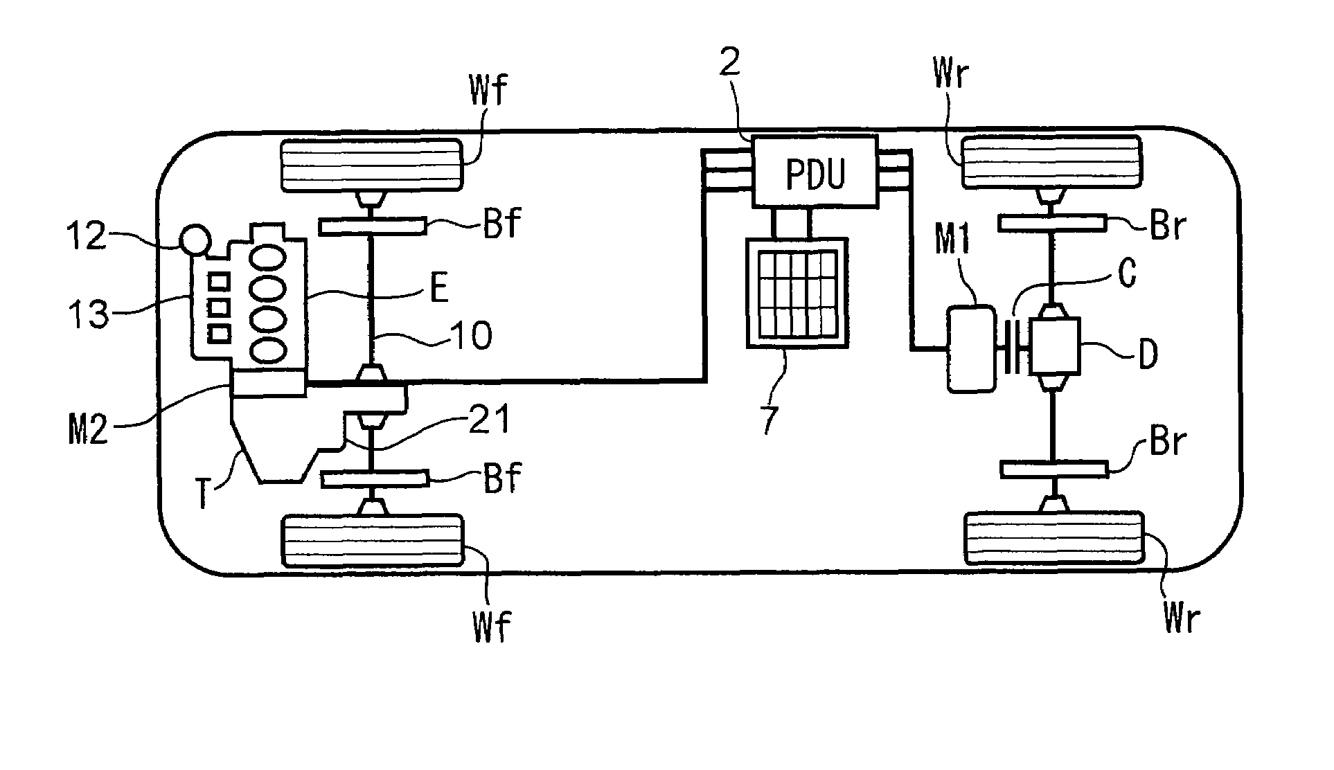
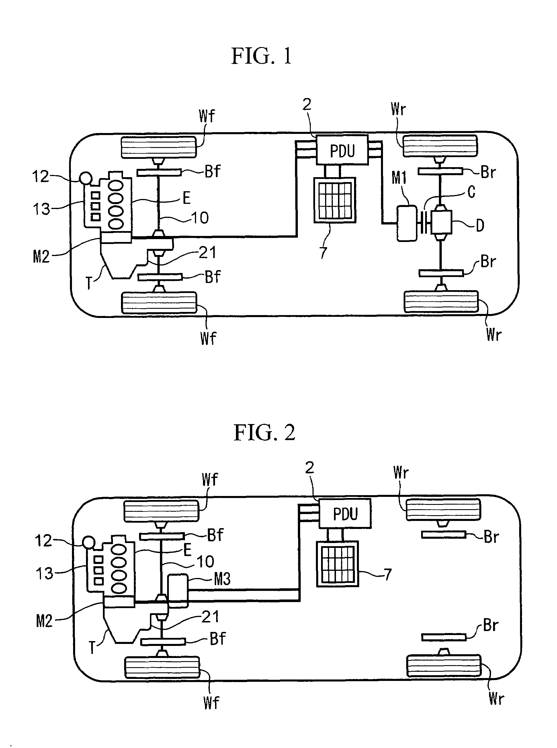
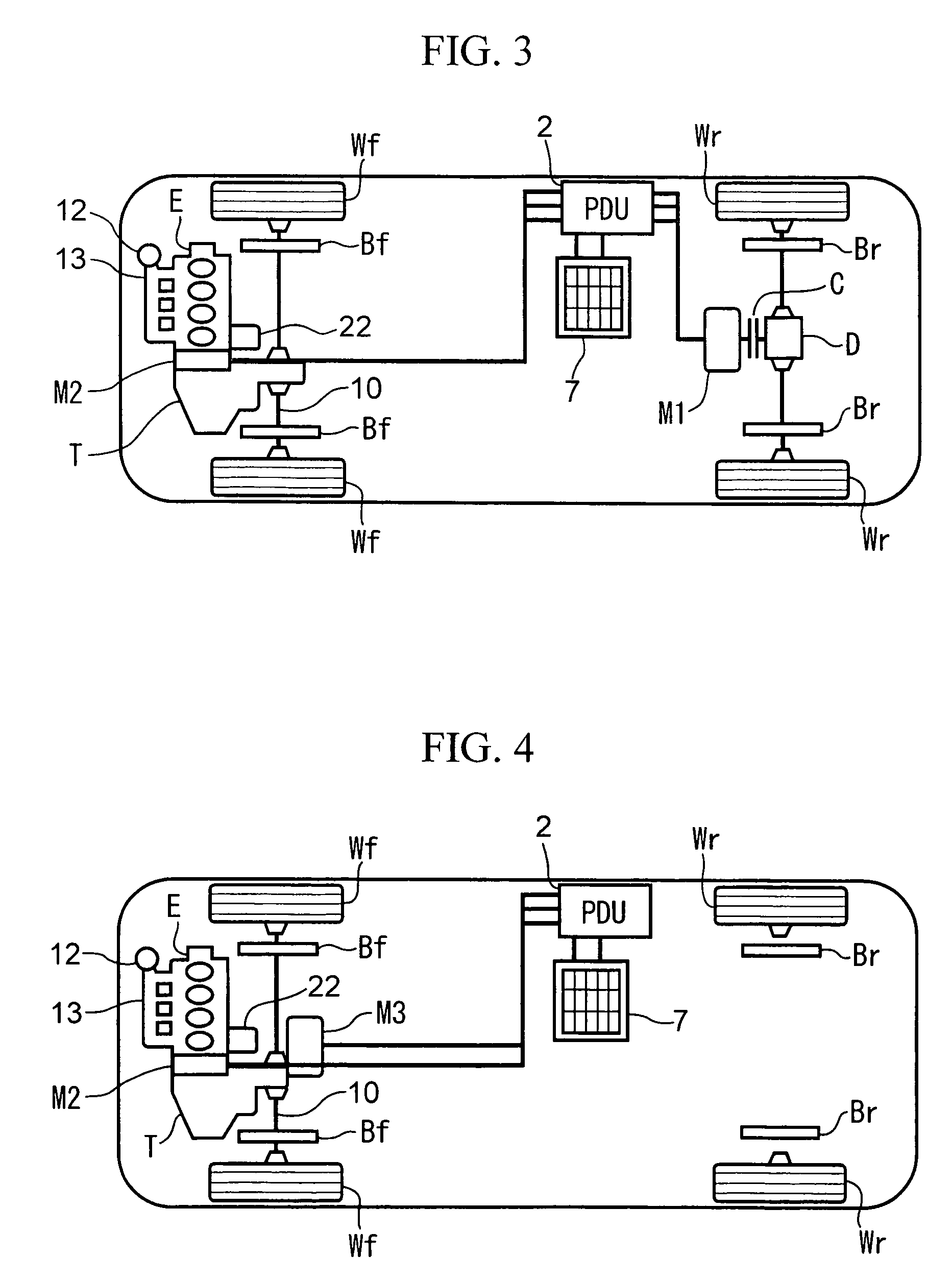
[0053]FIG. 1 is an overall block diagram of a hybrid vehicle to which the present invention is applied.

[0054]The hybrid vehicle shown in the figure is a four-wheel drive, including an engine E and a motor M2 on the front side, and including a motor M1 which is connected for example to an input side of a differential gear D on the rear side. In the present embodiment, the motor M1 on the rear side mainly works as a traction motor, and the motor M2 on the front side mainly works as a generator. Therefore, they are called traction motor M1 and generator motor M2 respectively in the description hereunder.

[0055]The generator motor M2 is arranged in a position sandwiched between the engine E and a transmission T (which may be an automatic transmission) having a speed-shifting clutch. Inside the transmission T, the speed-shift...


PUM


Abstract

An automatic transmission controller for a hybrid vehicle of the present invention is used for the hybrid vehicle being a four-wheel drive vehicle and including an engine and a generator motor on a front wheel side of the hybrid vehicle and a traction motor on a rear wheel side of the hybrid vehicle. The automatic transmission controller for a hybrid vehicle includes: an automatic transmission for transmitting a driving force from the engine to an output shaft of the hybrid vehicle; and an oil pump for supplying a speed-shifting clutch of the automatic transmission with pre-pressure to eliminate play of the speed-shifting clutch, when the hybrid vehicle is driven by a driving force from the traction motor.

Description

[0001]Priority is claimed on Japanese Patent Application No. 2004-41627, filed Feb. 18, 2004, the contents of which are incorporated herein by reference.BACKGROUND OF THE INVENTION[0002]1. Field of the Invention[0003]The present invention relates to an automatic transmission controller applied to a hybrid vehicle which includes an engine, a traction motor, and a generator motor, and can travel by the driving force from the individual traction motor, or the driving force from the engine.[0004]2. Description of Related Art[0005]Recently, there is known a hybrid vehicle wherein one of the pair of front or rear main driving wheels are driven by an engine and the other pair of front or rear sub driving wheels are driven by a motor that is connected to a battery.[0006]In such a hybrid vehicle, the amount of fuel consumption and the exhaust gas can be decreased by selectively using the engine and the motor according to the operating state.[0007]As this kind of hybrid vehicle, there is a ve...

Claims


Application Information

Patent Timeline
Patent Type & Authority Patents(United States)
IPC IPC(8): B60K1/00B60K17/00B60K17/34B60K6/00B60W10/00B60W10/04B60W10/10B60K6/44B60W20/00B60K6/52B60K6/547B60K17/356B60L50/16B60W10/06B60W10/08B60W10/30F16D48/02F16H61/00F16H63/50
CPCB60W10/08B60W10/10B60W10/30B60K6/52B60W20/00Y10T477/6203Y10T477/60Y10T477/638Y02T10/6265B60L3/0061B60L3/12B60L7/14B60L15/2009B60L15/2045B60L2210/10B60L2210/30B60L2210/40B60L2240/12B60L2240/421B60L2240/423B60L2260/28B60L50/61B60L50/16B60L58/12B60L58/21B60L58/20B60L50/66Y02T10/62Y02T10/64Y02T10/70Y02T10/72Y02T10/7072B60W10/119B60W10/02B60W10/06
Inventor YAMAMOTO, AKIHIROYAMAMOTO, KAZUHISA
Owner HONDA MOTOR CO LTD
Why Eureka
Try Eureka