Differential pressure-driven borohydride based generator

a technology of borohydride and generator, which is applied in the direction of liquid degasification, physical/chemical process catalyst, separation process, etc., can solve the problems of limited use, insufficient or impractical hydrogen storage methods, and insufficient hydrogen storage for wide-spread consumer applications, so as to reduce the differential pressure load of the pump

Inactive Publication Date: 2008-01-08
SILICON VALLEY BANK
View PDF25 Cites 29 Cited by
  • Summary
  • Abstract
  • Description
  • Claims
  • Application Information

AI Technical Summary

Benefits of technology

[0008]It is a further object of the invention to provide a hydrogen generation system which can be used to augment of a hydrogen generation system containing an electrically powered pump by reducing the differential pressure load on the pump.

Problems solved by technology

Several methods of storing hydrogen currently exist but are either inadequate or impractical for wide-spread consumer applications.
Cryogenic storage provides a volume density of 70 grams of hydrogen per liter, but is limited further by the weight of tanks required for storage which limits its use for consumer applications.
Finally, liquid hydrogen is not safe or practical for most consumer applications.
However, a 100 pound steel cylinder can only store about one pound of hydrogen at about 2200 psi, which translates into 1% by weight of hydrogen storage.

Method used


Image

  • Differential pressure-driven borohydride based generator
  • Differential pressure-driven borohydride based generator
  • Differential pressure-driven borohydride based generator

Examples


example 1

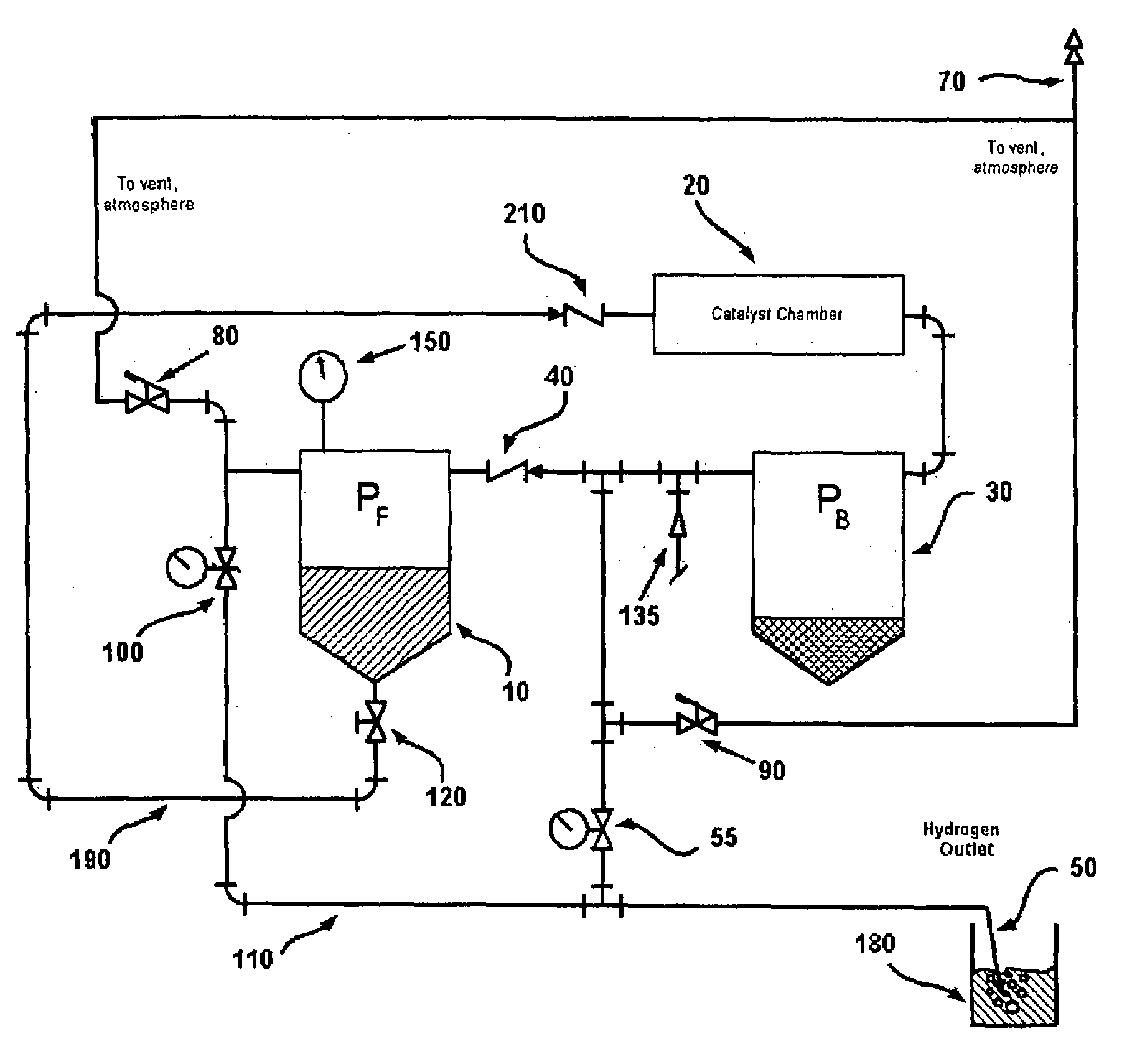
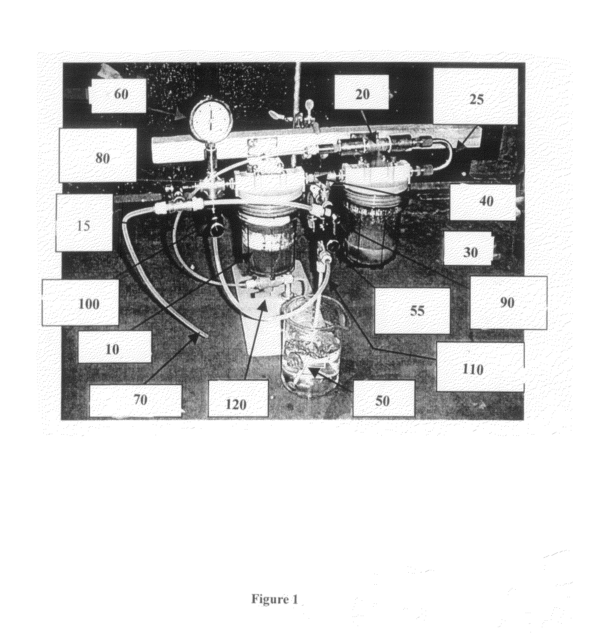
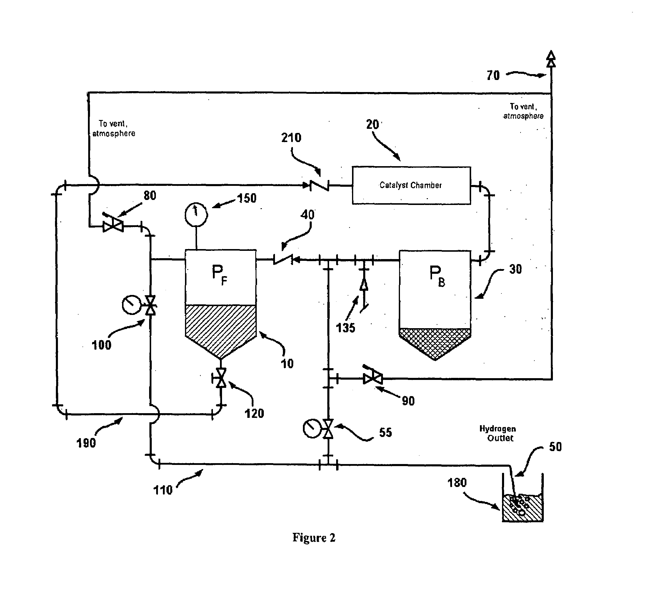
[0025]A schematic diagram of the arrangement in FIG. 1 according to the invention is shown in FIG. 2. A fuel solution comprising 20% NaBH4 by weight, 3% NaOH by weight, and 77% H2O by weight was poured into fuel vessel 10 such that approximately half the vessel was filled with solution. An initial pressure was supplied to the system by introducing N2 gas through line 135 with regulator valve 55 in a closed position. Note that the source of the initial pressure is not limited to N2 gas; for example, it could alternatively be H2 gas arising from forcing a small amount of fuel over the catalyst. The pressure gauge 150 read 15 psi. The fuel shut-off valve 120 was opened and as expected, no pressure drop was observed. To initiate hydrogen generation, regulator valve 55 was opened about halfway. Gas began to flow out of outlet line 50 as evidenced by the appearance of bubbles in water beaker 180. Very soon after the bubbling began, fuel was observed moving through the fuel inlet line 190 ...


PUM

PropertyMeasurementUnit
pressuresaaaaaaaaaa
pressureaaaaaaaaaa
surface temperatureaaaaaaaaaa

Abstract

An arrangement for generating hydrogen gas utilizes differential pressure to transport fuel and spent fuel components without requiring an electrically powered fuel delivery pump.

Description

FIELD OF THE INVENTION[0001]The invention relates to a method and arrangement for generating hydrogen gas using a catalyst from a fuel such as borohydride. More particularly, the invention relates to a method and arrangement in which fuel is delivered to a catalyst chamber by means of internally generated differential pressure without requiring an elaborate electrically powered pumping system.BACKGROUND OF THE INVENTION[0002]Hydrogen is a “clean fuel” because it can be reacted with oxygen in hydrogen-consuming devices, such as a fuel cell or combustion engine, to produce energy and water. Virtually no other reaction byproducts are produced in the exhaust. As a result, the use of hydrogen as a fuel effectively solves many environmental problems associated with the use of petroleum based fuels. Safe and efficient storage of hydrogen gas is, therefore, essential for many applications that can use hydrogen. In particular, minimizing volume, weight and complexity of the hydrogen storage ...

Claims


Application Information

Patent Timeline
Patent Type & Authority Patents(United States)
IPC IPC(8): B01F7/08B01J8/08B01J7/00B01J8/02C01B3/04C01B3/06
CPCB01J8/0207B01J8/0278C01B3/065B01J2208/00539B01J2219/00038B01J2219/0027Y02E60/362Y02E60/364F17C11/005Y02E60/32Y02E60/36C01B3/06
Inventor AMENDOLA, STEVEN C.MOHRING, RICHARD M.PETILLO, PHILLIP J.FENNIMORE, KEITH A.PETILLO, STEPHEN C.
Owner SILICON VALLEY BANK
Why Eureka
Try Eureka