Ceramic foam insulator with thermal expansion joint

a ceramic foam insulator and thermal expansion joint technology, which is applied in the direction of gravity filters, loose filtering material filters, filter regeneration, etc., can solve the problems of particle entanglement in air streams that create significant transport problems in manufacturing environments, and the treatment of effluent gases is an ongoing problem

Inactive Publication Date: 2008-01-08
PORVAIR
View PDF18 Cites 37 Cited by
  • Summary
  • Abstract
  • Description
  • Claims
  • Application Information

AI Technical Summary

Benefits of technology

[0009]It is an object of the present invention to provide a porous ceramic comprising expansion zones allowing expansion and contraction of the ceramic without creating open passages or regions of significant thickness alterations.

Problems solved by technology

Treatment of effluent gases is an ongoing problem in the chemical industry.
When highly corrosive materials are utilized, or generated, the problem is magnified.
Particles entrained in an air stream create significant transport problems in a manufacturing environment.
Any area of flow disruption or transition tends to cause the particles to settle.
As particles settle they further disrupt flow thereby increasing the rate of particle settling.
This is not only undesirable but it is also potentially hazardous when corrosive or environmentally hazardous materials are involved.
Unfortunately, the structure still has deficiencies which have limited the use in certain instances.
As would be readily realized the expansion and contraction leads to structural cracks and eventual breakage of the porous ceramic interior walls.
This is highly undesirable due to the cost and the down time associated with replacing the ceramic.
For the present application expansion slots have not been considered acceptable since the slot provides passage for particles into the annular interior volume between the interior porous ceramic wall and the exterior wall.
Furthermore, an expansion slot provides a low resistance flow path for the air thereby disrupting the flow through the ceramic and defeating the benefit provided by the porous ceramic.
It has heretofore been considered impossible to provide an expansion slot in a porous ceramic without substantially altering the thickness of the ceramic in any way or without creating areas of low, or no, air flow through the porous ceramic.

Method used


Image

  • Ceramic foam insulator with thermal expansion joint
  • Ceramic foam insulator with thermal expansion joint
  • Ceramic foam insulator with thermal expansion joint

Examples


Embodiment Construction

[0024]The present invention will be described with reference to the various non-limiting drawings forming an integral part of the disclosure. In the drawings similar elements will be numbered accordingly. Unless otherwise specified percent density is percent density by weight versus theoretical maximum density.

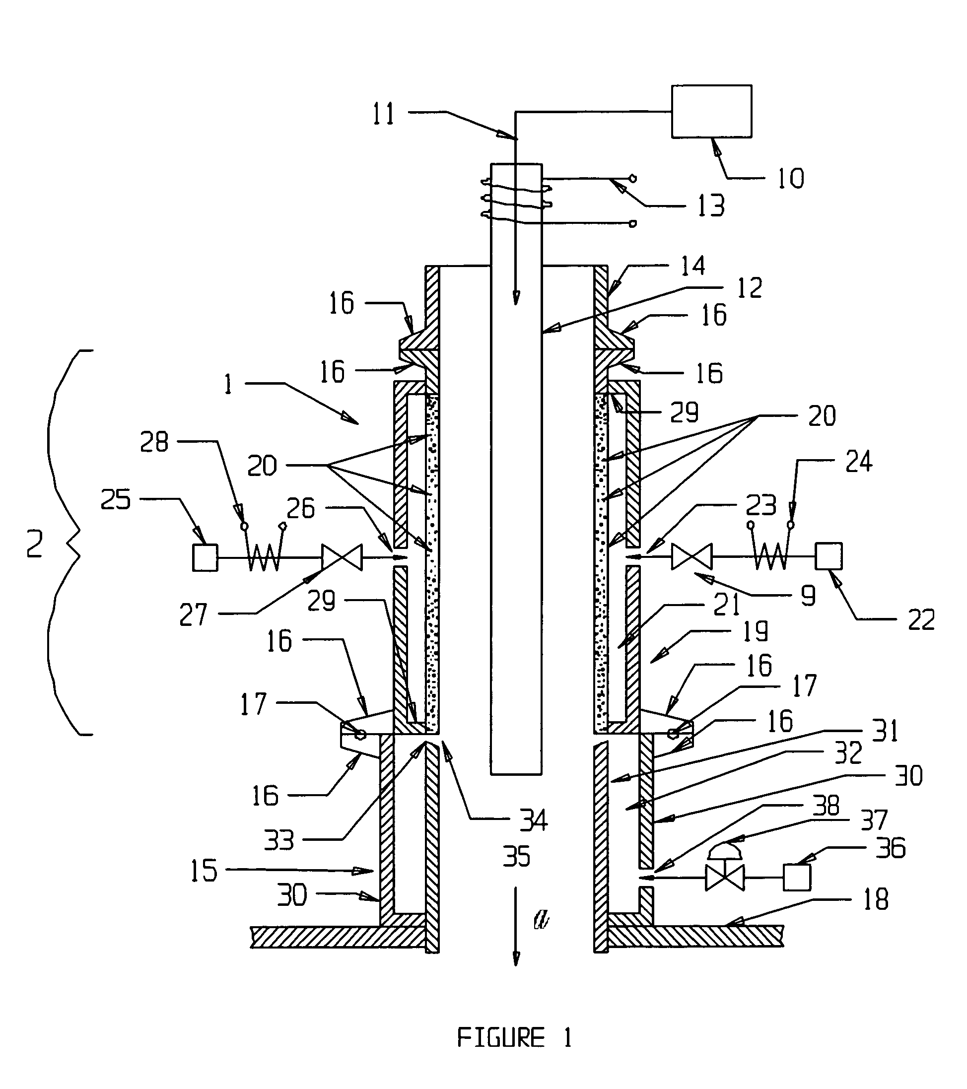
[0025]A process inlet of the present invention is generally represented at 1 of FIG. 1. A process element, 10, generates a waste stream comprising solids and effluent gas. The waste stream passes through a conduit, 11, in the direction of the arrow, a, into an inner tubular member, 12. Thermal control devices, 13, may be employed as would be realized. A canister, 2, is connected between an upper process tube, 14, and lower process tube, 15, by mating flanges, 16, preferably with a seal, 17, such as an O-ring seal. The upper process tube, 14, provides connectivity between the process element, 10, and the canister, 2. The lower process tube, 15, provides connectivity between the...


PUM

PropertyMeasurementUnit
angleaaaaaaaaaa
angleaaaaaaaaaa
angleaaaaaaaaaa

Abstract

A canister for maintaining entrained particles in a gas stream passing there through. The canister has an outer annular member and an inner porous annular member. The inner porous annular member has rings with at least one expansion zone in each ring. An annular interior volume is between the outer annular member and the inner porous annular member. A gas source is in flow communication with the annular interior volume for providing gas at a pressure sufficient to pass through the inner porous annular member to dislodge particles adhering thereto.

Description

CROSS-REFERENCE TO RELATED APPLICATIONS[0001]This application claims priority to U.S. Provisional Patent Appl. No. 60 / 543,013 filed Feb. 9, 2004 which is pending.BACKGROUND OF THE INVENTION[0002]The present invention is related to a ceramic foam insulator with a thermal expansion zone. More particularly, the present invention is related to an effluent gas treatment inlet system with ceramic foam insulator comprising a constant thickness thermal expansion zone.[0003]Treatment of effluent gases is an ongoing problem in the chemical industry. Virtually every chemical process has materials which are undesirable and which must be neutralized, diluted or captured. When highly corrosive materials are utilized, or generated, the problem is magnified.[0004]Particles entrained in an air stream create significant transport problems in a manufacturing environment. It is preferable to insure that all particles remain entrained until reaching the effluent gas treatment zone wherein the particles ...

Claims


Application Information

Patent Timeline
Patent Type & Authority Patents(United States)
IPC IPC(8): B01D35/00B01D46/00
CPCB01D46/24
Inventor REDDEN, MYRON K.OLSON, III, RUDOLPH A.
Owner PORVAIR
Why Eureka
Try Eureka