Frequency synthesizer
a frequency synthesizer and synthesizer technology, applied in the direction of oscillator generators, pulse automatic control, pulse techniques, etc., can solve the problems of increasing prolonging the lockup time required before the pll locks, and increasing the current consumption and apparatus area
- Summary
- Abstract
- Description
- Claims
- Application Information
AI Technical Summary
Benefits of technology
Problems solved by technology
Method used
Image
Examples
first embodiment
(1) FIRST EMBODIMENT
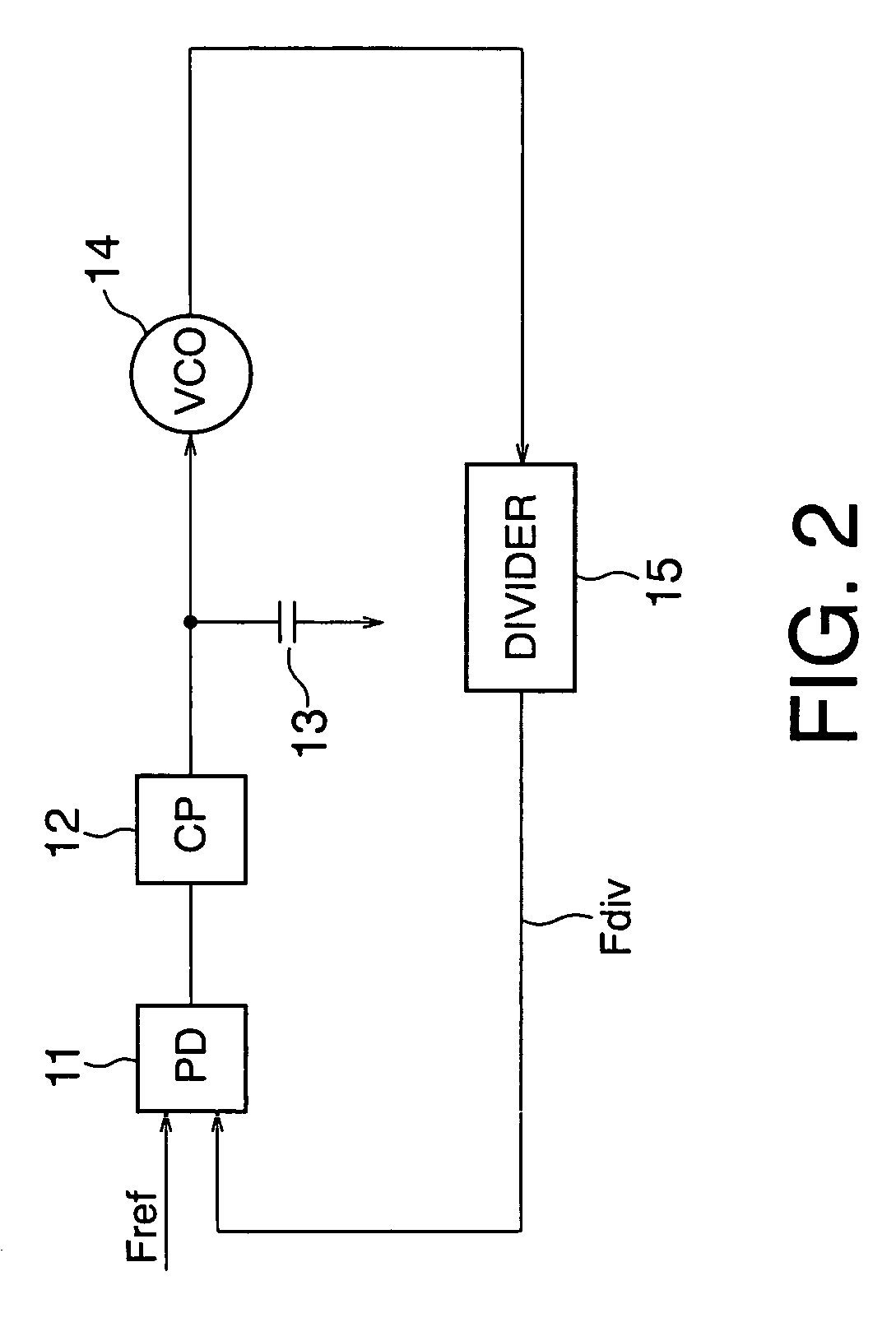
[0066]FIG. 2 shows the arrangement of a PLL as a comparative example.
[0067]A phase detector (to be referred to as a PD hereinafter) 11 compares the phase of a signal having a frequency Fdiv divided by a divider 15 having a frequency dividing ratio N (N>0) with the phase of a signal having a reference frequency Fref supplied by, e.g., a CPU (not shown) which controls the whole system. The phase difference of the frequency Fdiv from the reference frequency Fref is output as the comparison result.
[0068]On the basis of this comparison result, a charge pump (to be referred to as a CP hereinafter) 12 charges or discharges the output terminal, and outputs a control voltage Vctrl based on the comparison result. A loop filter 13 which ensures the stability of the loop is inserted between this output terminal and the ground terminal.
[0069]A VCO 14 is given the control voltage Vctrl output from the CP 12, and outputs an oscillation frequency Fvco based on this voltage.
[0070...
second embodiment
(2) SECOND EMBODIMENT
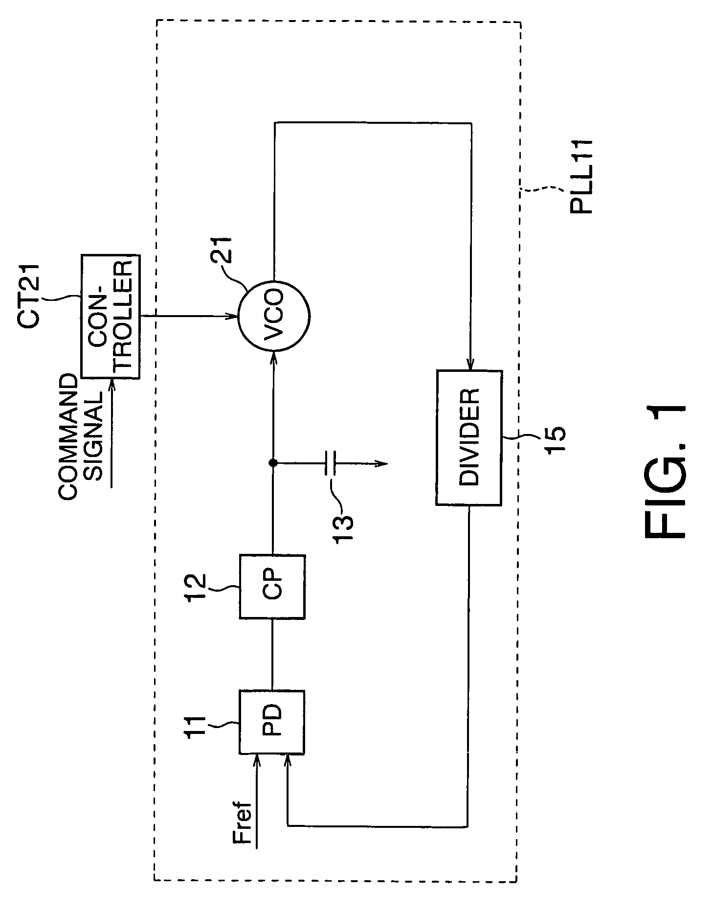
[0098]A frequency synthesizer according to the second embodiment of the present invention will be described below with reference to FIG. 12 showing the arrangement of this frequency synthesizer.
[0099]In the first embodiment shown in FIG. 1, a command signal is supplied to the controller CT21 from a CPU (not shown) or the like. On the basis of this command signal, a control signal is given to the VCO 21, and ON / OFF of each of the switches SW1 to SWn contained in the VCO 21 is controlled. As a consequence, the capacitances C1 to Cn shown in FIG. 6, for example, are selectively added in parallel with the variable capacitance Cv.
[0100]By contrast, in this embodiment, a comparator COM41 compares a control voltage Vctrl, which is output from a CP 12 to a VCO 21, with a reference voltage Vref1, and supplies the comparison result to a controller CT41. On the basis of this comparison result, the controller CT41 supplies a control signal to the VCO 21. In the VCO 21, ON / O...
third embodiment
(3) THIRD EMBODIMENT
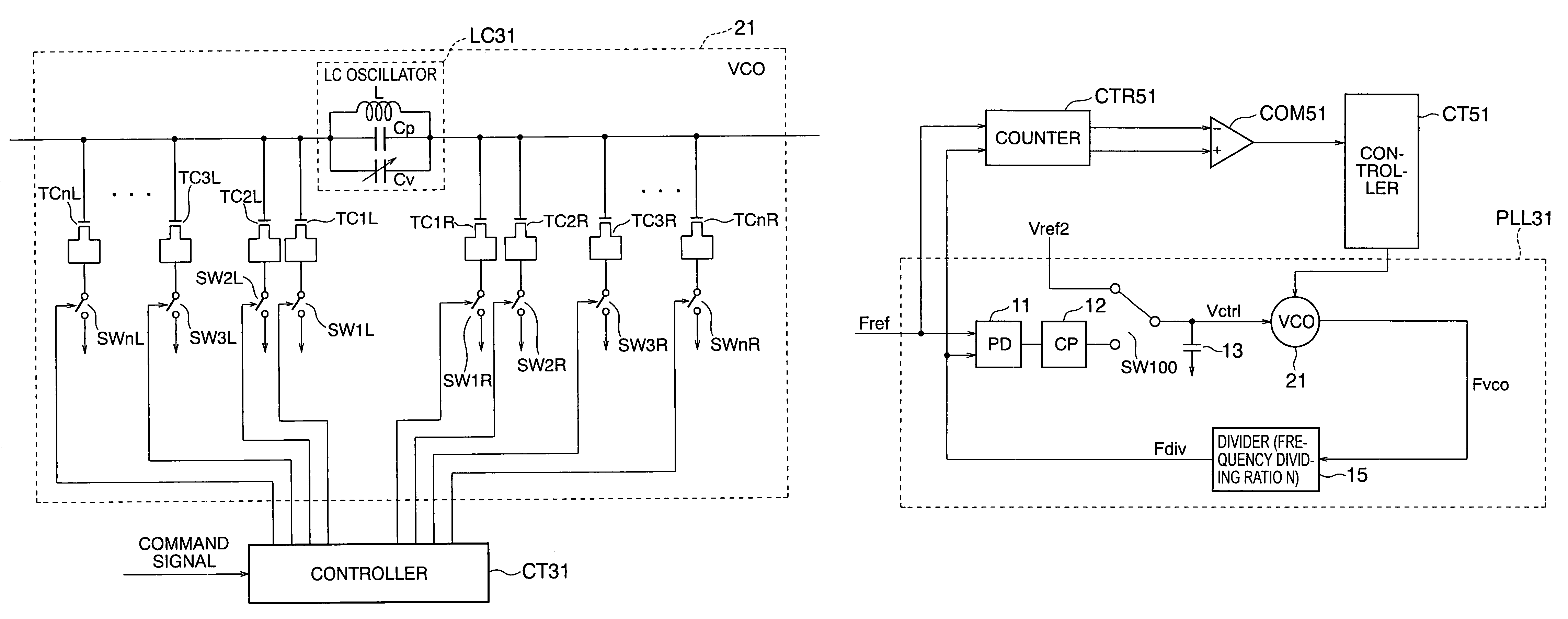
[0125]A frequency synthesizer according to the third embodiment of the present invention will be described below with reference to FIG. 17 showing the arrangement of this frequency synthesizer.
[0126]This embodiment includes a PD 11, a CP 12, a loop filter 13, a VCO 21, a divider 15, a PLL 31 having a voltage switch SW100 which connects the output terminal of the CP 12 or a reference voltage Vref2 to the input terminal of the loop filter 13, a counter CTR51, a comparator COM51, and a controller CT51.
[0127]Before the voltage switch SW100 connects the output terminal of the CP (Charge Pump) 12 to the input terminal of the loop filter 13 and the PLL 31 starts a normal operation, the output terminal of the CP 12 and the input terminal of the loop filter 13 are separated to form an open loop. The reference voltage Vref2 is input to the input terminal of the loop filter 13, and a control voltage Vctrl is applied to the VCO 21 via the loop filter 13. Reference symbol Fvc...
PUM
 Abstract
Description
Claims
Application Information
 - R&D
- Intellectual Property
- Life Sciences
- Materials
- Tech Scout
- Unparalleled Data Quality
- Higher Quality Content
- 60% Fewer Hallucinations
Browse by: Latest US Patents, China's latest patents, Technical Efficacy Thesaurus, Application Domain, Technology Topic, Popular Technical Reports.
© 2025 PatSnap. All rights reserved.Legal|Privacy policy|Modern Slavery Act Transparency Statement|Sitemap|About US| Contact US: help@patsnap.com


