Three-axis integrated MEMS accelerometer

a three-axis, accelerometer technology, applied in the direction of speed/acceleration/shock measurement, measurement devices, instruments, etc., can solve the problems of preventing market growth of three-axis accelerometers, impeded market growth of three-dimensional accelerometers, etc., to achieve low cross-axis sensitivity, high sensitivity to acceleration, and low power consumption

Inactive Publication Date: 2008-01-15
VAGANOV VLADIMIR +1
View PDF6 Cites 79 Cited by
  • Summary
  • Abstract
  • Description
  • Claims
  • Application Information

AI Technical Summary

Benefits of technology

[0020]The 3D accelerometer for measuring three components of inertial force (or acceleration) vector with respect to an orthogonal coordinate system according to the present invention overcomes the disadvantages of prior art devices. A present invention describes a small-size single-die three-axis MEMS accelerometer that provides high sensitivity to acceleration, equal or comparable sensitivity to all three components of acceleration vector, low cross-axis sensitivity, low power consumption, high reliability and high long-term stability. This three-axis accelerometer has extremely low cost, especially in high volume production, due to a simple high-yield micromachining process fully compatible with IC processing, low-cost packaging based on wafer-level packaging and a simple testing process.

Problems solved by technology

However, available 3D accelerometers impede market growth because of their high cost.
Besides that, the described three-axis accelerometer does not provide means for protection of the accelerometer structure from shock overload.

Method used


Image

  • Three-axis integrated MEMS accelerometer
  • Three-axis integrated MEMS accelerometer
  • Three-axis integrated MEMS accelerometer

Examples


second embodiment

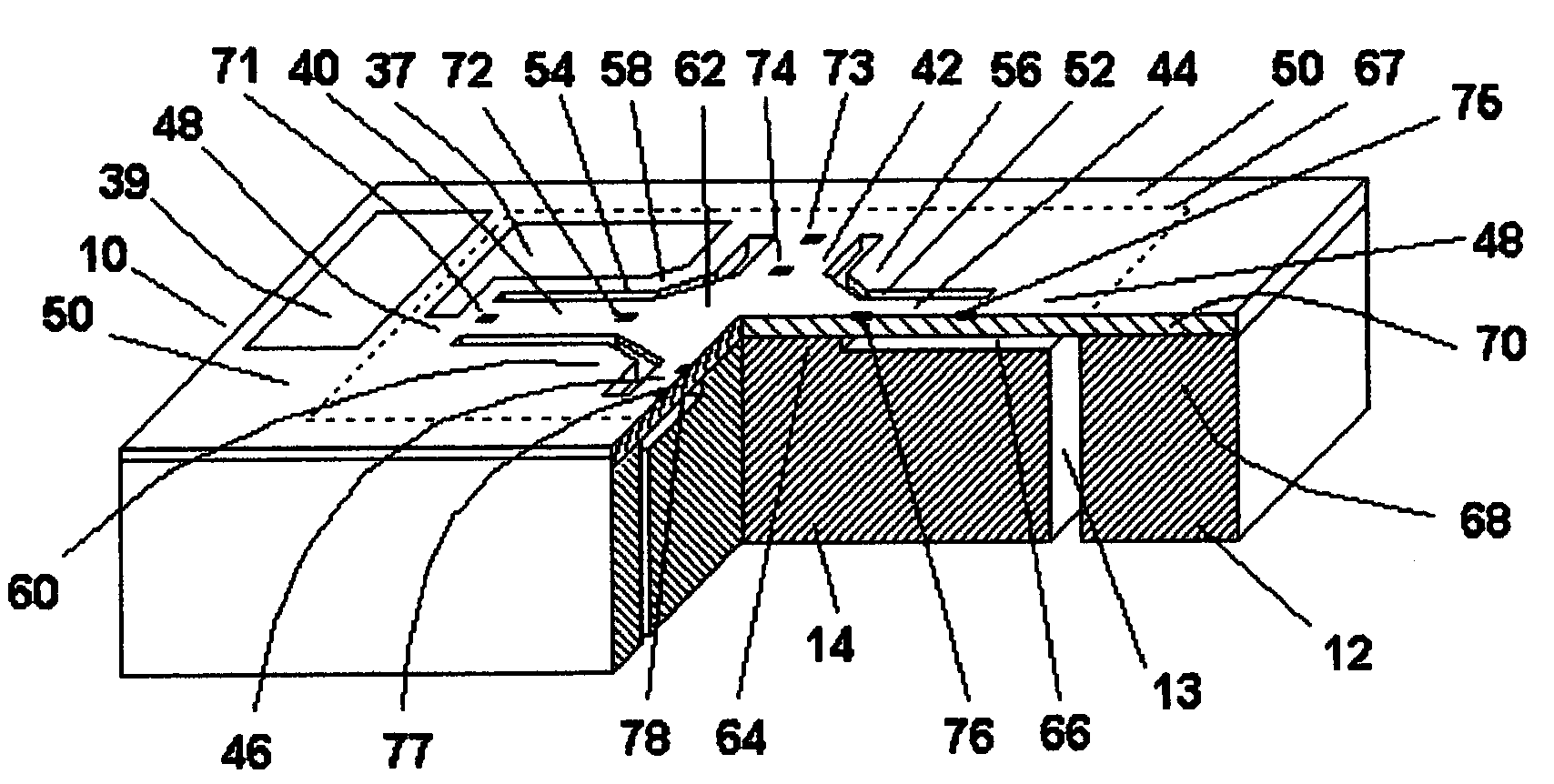
[0126]FIG. 2 shows mechanical structure of threeaxis accelerometer for determining components of an inertial force vector with respect to an orthogonal coordinate system according to the The sensor die 10 has side 1 and an opposite side 2 in the plane of a semiconductor substrate. The coordinate system (X, Y, Z axes) is chosen such that X and Y axes are located in the plane of side 1 and parallel to the sidewalls of the chip. The Z-axis is perpendicular to side 1 and the origin is located in the projection of a center of gravity of the proof mass onto the side 1. Each of X, Y, Z dimensions of the proof mass is defined as maximum difference between corresponding coordinates of any two points of the proof mass. The sensor die 10 is fabricated on a semiconductor substrate of SOI type having handle layer 68 and device layer 70. A buried cavity 66, or in general a set of cavities, is formed in the handle layer 68 at the interface of the handle and device layers. Mechanical structure of ...

third embodiment

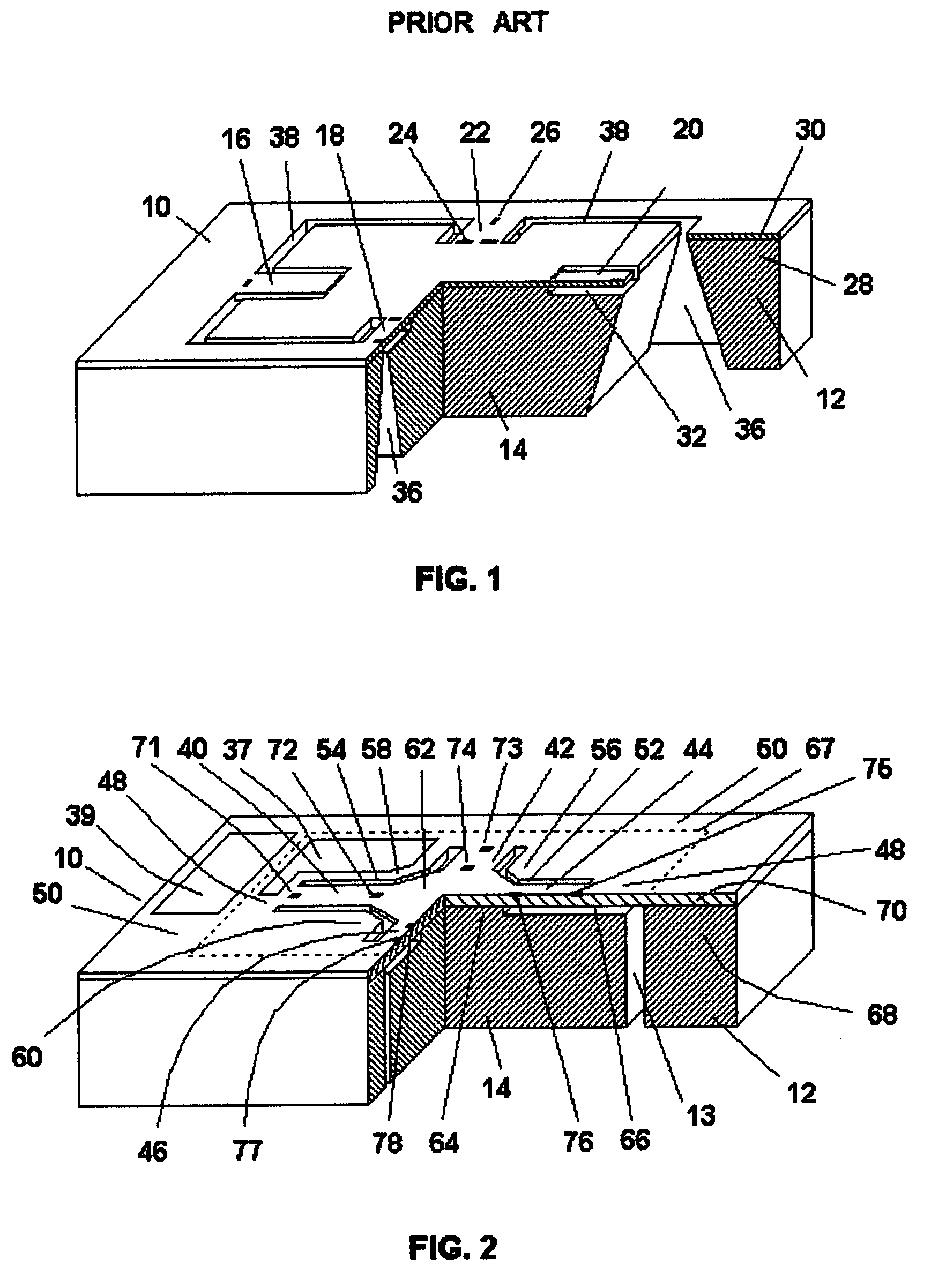
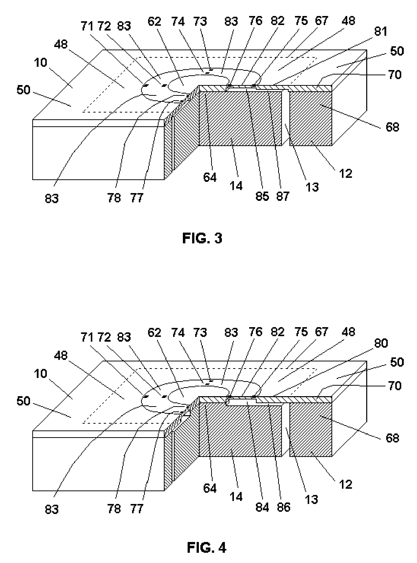
[0136]FIG. 3 and FIG. 4 show mechanical structures of three-axis accelerometer according to the

[0137]The sensor die 10 of three-axis accelerometer shown in FIG. 3 is fabricated on a semiconductor substrate of SOI type having handle layer 68 and device layer 70. A buried cavity 85, 87 are located in the device layer 70 at the interface of the handle and device layers. Mechanical structure of the three-axis accelerometer consists of a frame, a proof mass 14 and an elastic element In the form of an annular diaphragm 83. The frame has a thick portion 12 and a thin portion 48 having uniform thickness. The proof mass, being located within the thickness of SOI semiconductor substrate, is separated from the thick portion 12 of the frame by a slot 13, from the thin portion 48 of the frame by the buried cavity 87, and from the elastic element 82, 83 by the buried cavity 85. The annular diaphragm 83 is connected to the thin portion 48 of the frame on its outer edge and to the proof mass 14 at ...

fourth embodiment

[0144]FIG. 5 shows mechanical structure of three-axis accelerometer according to the The sensor die 10 is fabricated on a semiconductor substrate of SOI type having handle layer 68 and device layer 70. A buried cavity 86 is formed at the interface of the handle and device layers. Mechanical structure of the three-axis accelerometer consists of a frame, a proof mass 14 and an elastic element in the form of a portion 82 of diaphragm 80. The frame has a thick portion 12 and a thin portion 48 having uniform thickness. The proof mass 14 is separated from the thick portion 12 of the frame by a slot 13 and from the thin portion 48 of the frame by the buried cavity 86. Stress-sensitive components 72, 74, and 76 are located on the elastic element 82.

[0145]The improvement made to the three-axis accelerometer according to the fourth embodiment is related to simplification of the structure and as a result of that decrease of its cost.

[0146]As it can be seen from FIG. 5, the proof mass is suspe...


PUM


Abstract

3D accelerometer for measuring three components of inertial force (or acceleration) vector with respect to an orthogonal coordinate system, which has high sensitivity due to a big proof mass located within a cavity beneath the surface of the sensor die. The size of the cavity and the size of the proof mass exceed the corresponding overall dimensions of the elastic element. The sensor structure occupies a very small area at the surface of the die increasing the area for ICs need to be integrated on the same chip.

Description

REFERENCES[0001]U.S. patent documents1. 4,882,933November 1989Petersen et al. 73 / 5172. 4,967,605November 1990Okada 73 / 5173. 5,121,633June 1992Murakami et al. 73 / 5174. 5,182,515January 1993Okada 73 / 5175. 5,295,386March 1994Okada 73 / 5176. 5,485,749January 1996Nohara 73 / 517BACKGROUND OF THE INVENTION[0002]1. Field of the Invention[0003]This invention relates to semiconductor devices, Micro Electro Mechanical Systems (MEMS), sensors and more specifically to three dimensional (3D) three-axis accelerometers, vibration sensors and inclinometers for consumer and other applications.[0004]2. Description of the Related Art[0005]MEMS accelerometers are known for more than 30 years and they are widely used in different areas. Automotive air-bag applications currently represent the biggest MEMS accelerometer market.[0006]There are only few known MEMS three-axis (or 3D) accelerometers that can measure all three components of an acceleration vector.[0007]The market for 3D accelerometers includes ha...

Claims


Application Information

Patent Timeline
Patent Type & Authority Patents(United States)
IPC IPC(8): G01P15/08
CPCG01P15/123G01P15/18G01P2015/084
Inventor VAGANOV, VLADIMIRBELOV, NICKOLAI
Owner VAGANOV VLADIMIR
Why Eureka
Try Eureka