
Fuel cell system utilizing control of operating current to adjust moisture content within fuel cell

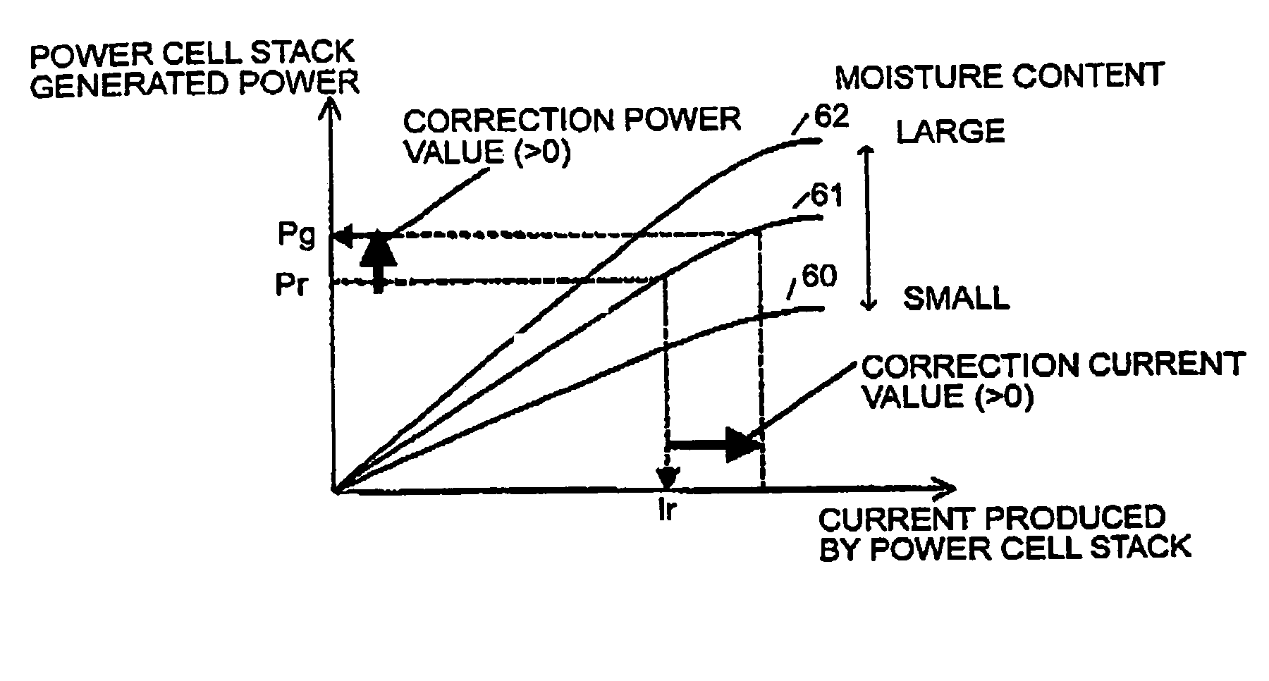
a fuel cell and control current technology, applied in the direction of secondary cell servicing/maintenance, electrochemical generators, transportation and packaging, etc., can solve the problem of difficulty in drying the interior of the fuel cell, the level of electric power produced by the fuel cell to be lowered, and the inability to maintain the fuel cell in a suitable internal moisture condition. , to achieve the effect of reducing the level of electric power produced by the fuel cell, and improving the service li

Inactive Publication Date: 2008-01-15
DENSO CORP
View PDF11 Cites 6 Cited by
  • Summary
  • Abstract
  • Description
  • Claims
  • Application Information

AI Technical Summary

Benefits of technology

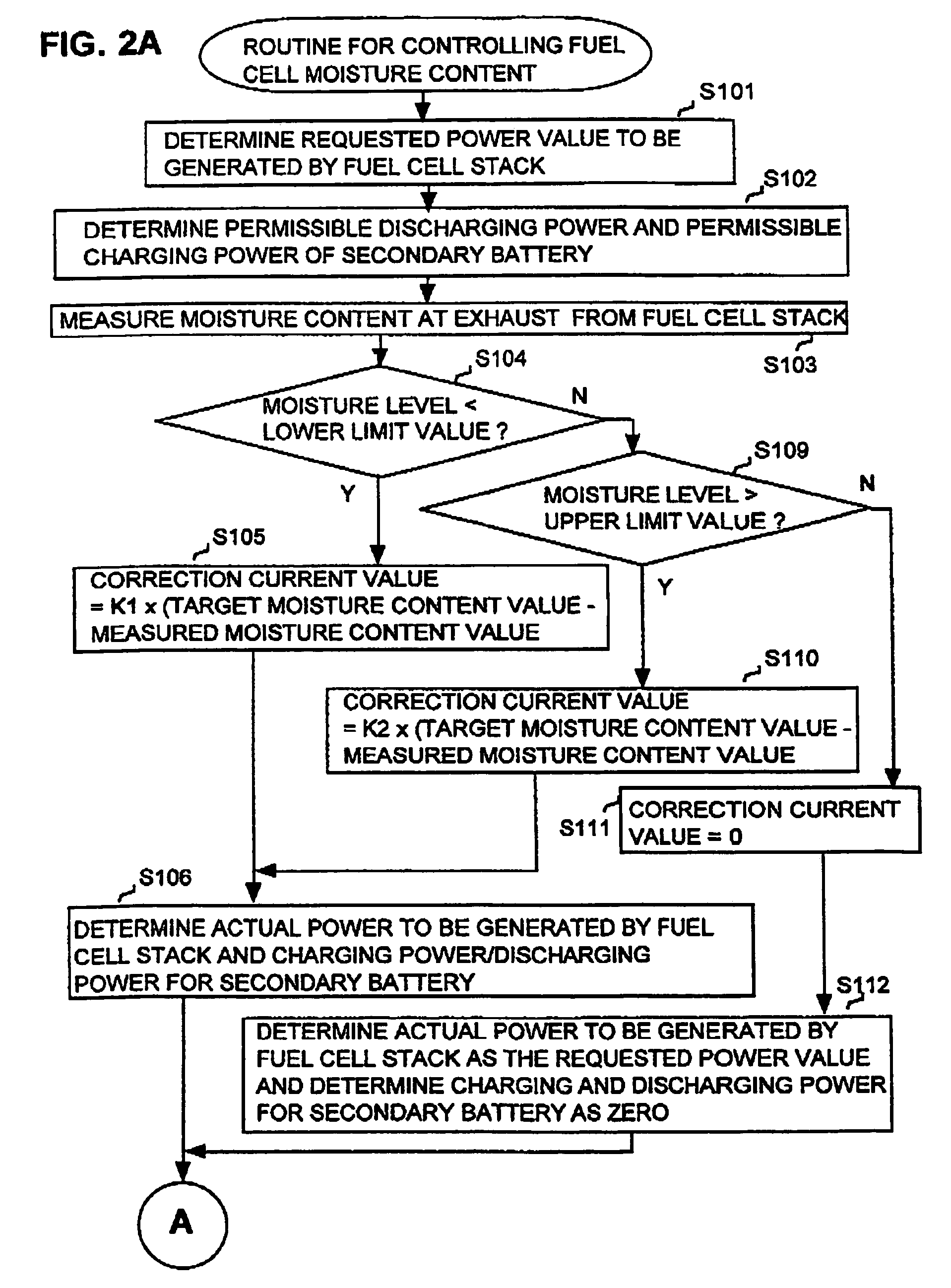
The present invention provides a fuel cell system for generating power that maintains an optimal moisture content in the fuel cell generating section. This is achieved by monitoring the moisture content and adjusting the operating current of the fuel cell generating section to compensate for any excess or insufficiency of moisture content. The system includes a controllable power source that compensates for any changes in power generated by the fuel cell generating section. The system also includes a moisture diagnosis sensor and memory means to store data for different moisture content values and their corresponding electric current or power values. The control means reads the data from the memory means to adjust the fuel cell generating section to maintain the desired power output. Overall, the invention provides a fuel cell system that continuously generates power at a specific required value, regardless of changes in fuel cell current or other factors.

Problems solved by technology

Conversely, if there is an excessive amount of water contained in the anode and cathode electrodes, then this obstructs the electrochemical reactions which occur at the surfaces of these electrodes, so that this also causes the level of electric power produced from the fuel cell to be lowered.
However when such a prior art method is applied, since the rate at which water is generated within the fuel cell does not decrease, it is difficult to dry the interior of the fuel cell.
Furthermore with such a prior art fuel cell system, no consideration is given to the problem of preventing excessive drying of the interior of the fuel cell, and so it is not possible to continuously maintain the fuel cell in a suitable condition of internal moisture.

Method used


Image

  • Fuel cell system utilizing control of operating current to adjust moisture content within fuel cell
  • Fuel cell system utilizing control of operating current to adjust moisture content within fuel cell
  • Fuel cell system utilizing control of operating current to adjust moisture content within fuel cell

Examples


first embodiment

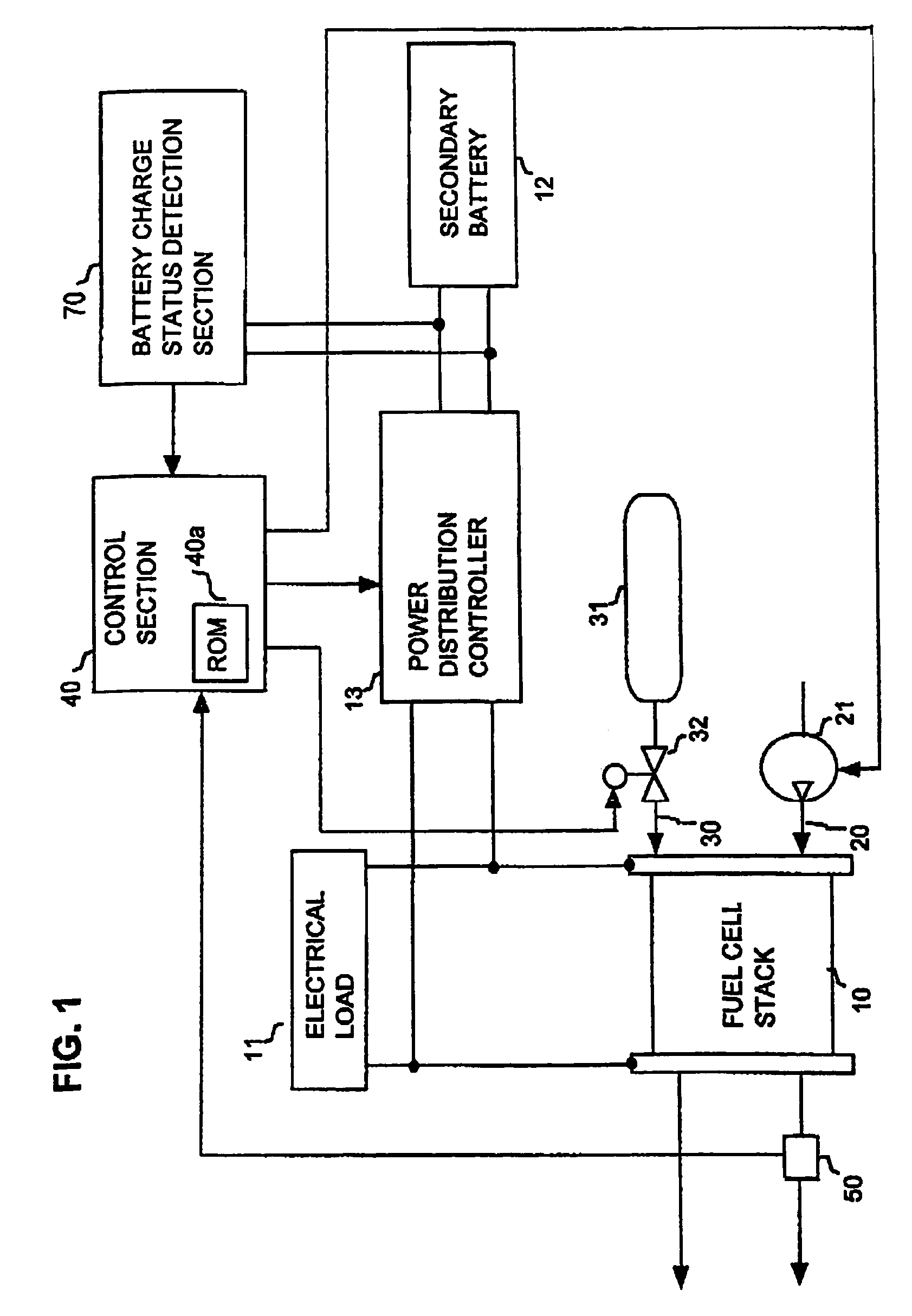
[0033]A first embodiment will be described referring to FIGS. 1 to 5. This embodiment is a fuel cell system that is utilized as the motive power source of an electric vehicle. FIG. 1 is a conceptual system diagram showing the overall configuration of the embodiment. As shown in FIG. 1, the system is based on a fuel cell stack (i.e., battery of series-connected fuel cells) 10, which generates power by an electrochemical reaction between hydrogen and oxygen. With this embodiment, a polymer fuel cell is used for each of the series-connected fuel cells of the fuel cell stack 10. Each of these fuel cells is made up of a pair of electrodes with an electrolyte membrane sandwiched between them. By supplying hydrogen and oxygen (i.e., as air) to the fuel cell stack 10, electrical energy is generated by the aforementioned electrochemical reaction. The reactions which occur at the respective electrodes are as follows:

[0034]At the hydrogen side: H2→2H++2e−

[0035]At the oxygen side: 2H++½O2+2e−→H...

second embodiment

[0072]A second embodiment of a fuel cell system will be described referring to FIG. 6 and FIGS. 7A, 7B. FIG. 6 is a conceptual system diagram of this embodiment, in which components corresponding to those of the embodiment of FIG. 1 are designated by identical reference numerals to those of FIG. 1, with further description of these being omitted. The system is based on two fuel cell stacks 10A, 10B, which are respectively separately controlled. Overall control of the system is performed by a control section 140, which controls each of the compressor 21, air distribution adjustment valve 22, hydrogen distribution adjustment valve 33 and power distribution controller 13. The flow of air from the compressor 21 is divided into two paths, at a location upstream from the air distribution adjustment valve 22 and the fuel cell stacks 10A, 10B, i.e., a flow path 20A which supplies a flow of air to the fuel cell stack 10A, and a flow path 20B which supplies a flow of air to the fuel cell stac...

third embodiment

[0088]A third embodiment of a fuel cell system will be described referring to the conceptual system diagram of FIG. 8 and the flow diagram constituted by FIGS. 9A, 9B. In FIG. 8, components corresponding to those of the embodiment of FIG. 6 are designated by identical reference numerals to those of FIG. 6, with further description of these being omitted in the following. As shown in FIG. 8, the system is based on two fuel cell stacks 10A, 10B which are respectively separately controlled, with a control section 240 performing overall control of the system, including control of respective levels of power that are produced by the fuel cell stacks 10A, 10B, by supplying command signals to the power distribution controller 113 designating respective values of operating current that are to be generated by the fuel cell stacks 10A, 10B so that the required values of generated power will be achieved, and with the power distribution controller 113 performing control of the respective operati...


PUM

PropertyMeasurementUnit
operating currentaaaaaaaaaa
currentaaaaaaaaaa
electric poweraaaaaaaaaa

Abstract

In a fuel cell system utilizing fuel cells which generate electric power by a reaction between oxygen and hydrogen, the moisture content within a fuel cell is adjusted to be brought within an appropriate range by adjusting the operating current of the fuel cell. The total amount of electric power generated by the system is maintained at a required value by supplying / obtaining electric power to / from a secondary battery as required, or by utilizing a plurality of separately controlled fuel cells (or fuel cell stacks) and increasing or decreasing the electric power generated by another fuel cell or stack that is currently operating with an appropriate moisture content.

Description

FIELD OF APPLICATION [0001]The present invention relates to a fuel cell system having fuel cells which generate power by a chemical reaction between oxygen and hydrogen, and which is suitable as a mobile electrical generator for vehicles, ships, etc., as a portable electrical generator, or as a small-scale to domestic electrical generator.RELATED PRIOR ART [0002]When a fuel cell is in operation, if there is an insufficient amount of water contained in the solid electrolyte membrane of the cell, then the conductivity of the solid electrolyte membrane is lowered, so that the level of electric power produced from the fuel cell is lowered. Conversely, if there is an excessive amount of water contained in the anode and cathode electrodes, then this obstructs the electrochemical reactions which occur at the surfaces of these electrodes, so that this also causes the level of electric power produced from the fuel cell to be lowered.[0003]With one prior art type of fuel cell system, when a w...

Claims


Application Information

Patent Timeline
Patent Type & Authority Patents(United States)
IPC IPC(8): H01M8/04H01M8/24H01M10/42H01M16/00H02J7/34
CPCH01M8/04291H01M8/04522H01M8/04604H01M8/04619H01M8/04753H01M8/0491H01M8/0494H01M8/04947H01M16/006H02J7/34H01M8/249H01M10/42H02J2001/004Y02E60/50H02J2300/30Y02E60/10
Inventor IMAMURA, TOMONORIIZUHARA, HIDESHI
Owner DENSO CORP
Learn More