

Sensor and magnetic field apparatus suitable for use in for unilateral nuclear magnetic resonance and method for making same
a magnetic field and sensor technology, applied in the field of nuclear magnetic resonance (nmr) experiments, can solve the problems of short signal lifetime, limited sample range that can be examined, low snr measurement, etc., and achieve the effect of high permeability and material permeability
Inactive Publication Date: 2008-01-15
UNIVERSITY OF NEW BRUNSWICK
View PDF11 Cites 18 Cited by
- Summary
- Abstract
- Description
- Claims
- Application Information
AI Technical Summary
Benefits of technology
"The invention is about a way to create a magnetic field that is uniform and controlled over a specific area. This is done by using a special arrangement of magnets and high permeability material. The method allows for the precise control of the magnetic field in a way that is not possible with traditional magnetic arrays. The result is a highly accurate and uniform magnetic field that can be used for various applications."
Problems solved by technology
While this facilitates high signal-to-noise (SNR) and spatially resolved magnetic resonance imaging (MRI), it limits the range of samples that can be examined.
Significant drawbacks exist with the NMR-MOUSE.
This results in short signal lifetimes, obscuring chemical shift information and resulting in low SNR measurements.
The strong nonlinearity of the gradients results in an ill defined sensitive volume precluding conventional spatially resolved measurements.
These effects limit the effective resolution of the sensor by obscuring the location and distribution of the spin population observed in a measurement.
Specially designed planar coils must be used, resulting in a decrease in sensitivity.
The drawback of this approach is that specific parameters (eg. size, position and strength of magnets) must be selected for the optimization and the parameter space must be empirically selected to suit the desired magnet topology.
Furthermore, conventional simulation techniques are computationally expensive, leading to long optimization times, and constraining the number of parameters that can be optimized.
Many methods of shaping the pole pieces to provide an optimal B0 topology have been proposed, however all deal with generating a homogeneous field between two magnets and cannot be directly applied to the unilateral case.
Method used
View moreImage
Smart ImageViewing Examples

Examples
example
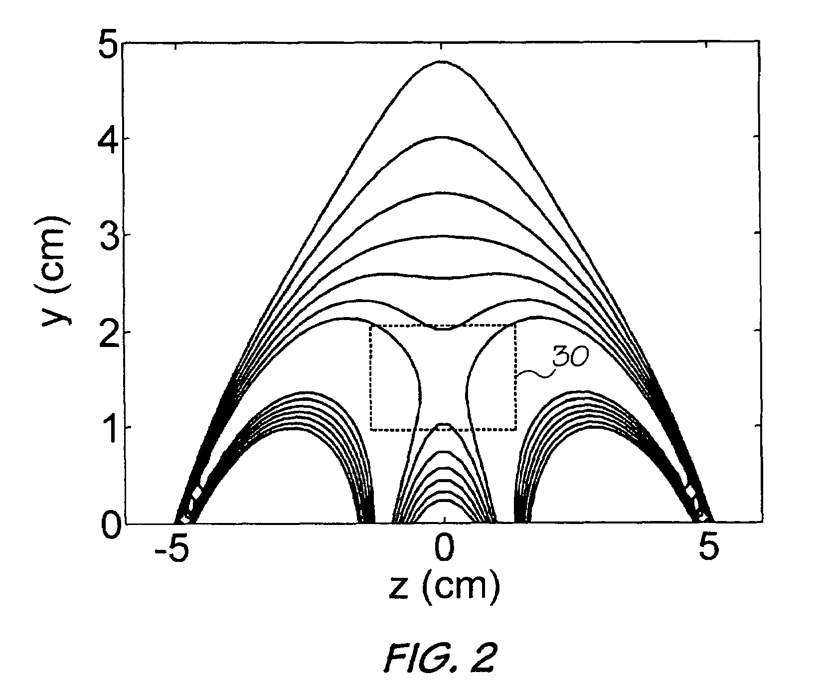
[0115]In the prototype GROUSE array shown in FIG. 16, the following design criteria was used:[0116]B0 normal to magnet surface;[0117]Gradient, G=˜30-50 Gauss / cm;[0118]Sensitive Spot 2.5 cm above magnet, pole pieces must fit within this region; and[0119]Gradient Linearity:
[0120]∂2B→0∂y2y=2.5=0
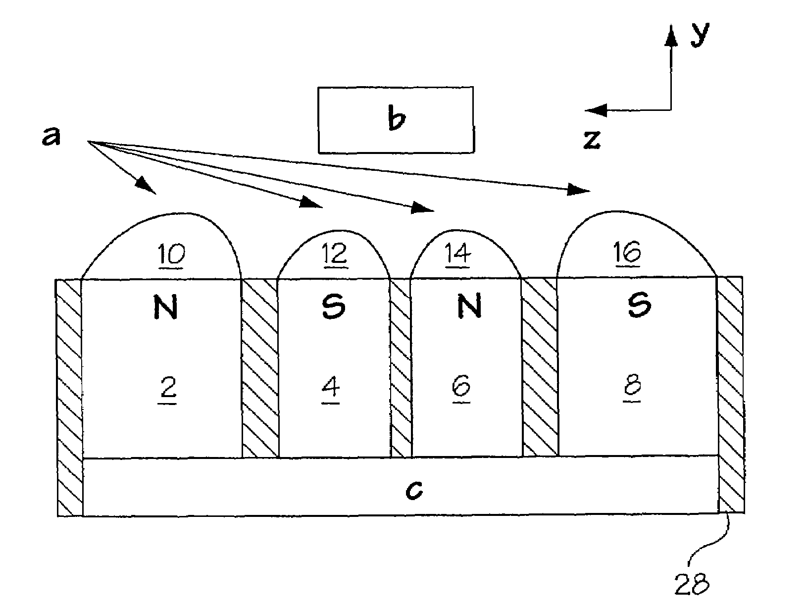
[0121]It will be understood that the methods of the invention can be used to design and construct a variety of unilateral magnet arrays and families of arrays including (1) a single magnet and single pole piece, which forms a linear gradient through the sensitive spot, (2) a four magnet array with four pole pieces which has a uniform sensitive spot and (3) a four magnet array with a uniform sensitive spot which lacks pole pieces entirely.
Login to View More PUM
 Abstract
A unilateral NMR sensor comprising a ferromagnetic yoke; a permanent magnet arranged on the yoke; a pole piece on the magnet; the pole piece including an air-pole piece interface surface whose shape corresponds to an equipotential contour of magnetic scalar potential.
Description
CROSS REFERENCE TO RELATED APPLICATIONS[0001]This application claims the benefit of U.S. Provisional Application Ser. No. 60 / 612,146, filed Sep. 23, 2004. This application also claims priority to and the benefit of Canadian Application Serial No. 2,530,563 filed on Sep. 19, 2005.BACKGROUND OF THE INVENTION[0002]In a conventional nuclear magnetic resonance (NMR) experiment, the sample under study is placed in a homogeneous magnetic field produced by a superconducting solenoid. While this facilitates high signal-to-noise (SNR) and spatially resolved magnetic resonance imaging (MRI), it limits the range of samples that can be examined. In recent years, this limitation has been addressed by the introduction of ‘inside out’ or unilateral NMR sensors in which, the fringe field from a permanent magnet array is used to generate the static B0 field in a volume displaced (remote) from the device. A surface coil or an alternate RF probe geometry is used to generate a remote B1 field. The shape...
Claims
Login to View More Application Information
Patent Timeline
 Patent Type & AuthorityPatents(United States)
IPC IPC(8): G01V3/00
CPCG01R33/3808
InventorBALCOM, BRUCE J.MARBLE, ANDREW E.MASTIKHIN, IGOR V.COLPITTS, BRUCE
OwnerUNIVERSITY OF NEW BRUNSWICK