
Air purged optical densitometer

a technology of optical densitometer and air purged, which is applied in the field of advanced gas purged optical densitometer, can solve the problems of significant reduction of densitometer accuracy, increased cost, and increased difficulty in detecting optical components, so as to reduce the probability of optical component contamination and reduce the probability of unstable optical path

Inactive Publication Date: 2008-01-15
HONEYWELL INT INC
View PDF17 Cites 16 Cited by
  • Summary
  • Abstract
  • Description
  • Claims
  • Application Information

AI Technical Summary

Benefits of technology

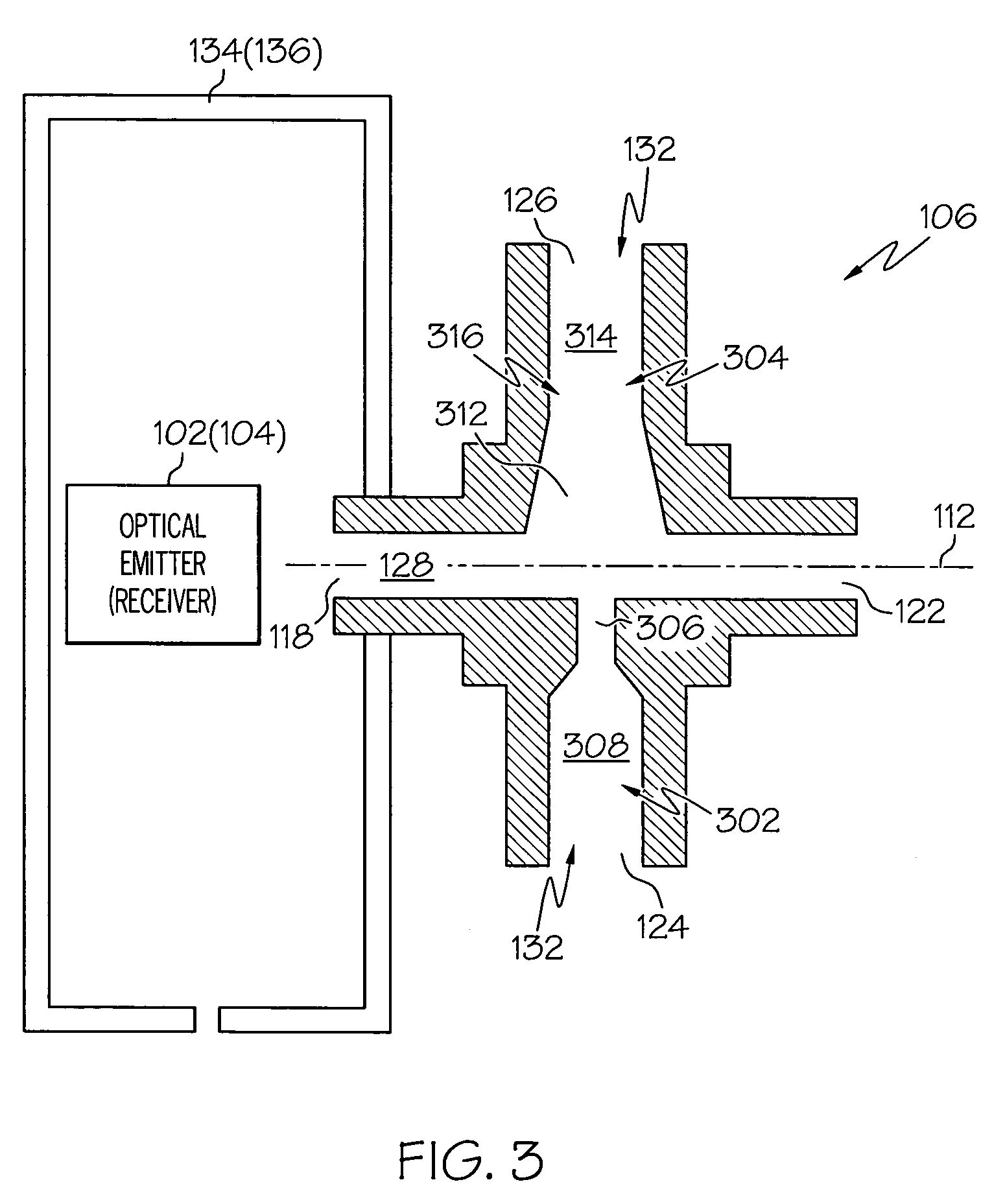
The present invention is an improved gas purged optical densitometer that reduces the likelihood of contamination and unstable optical path reductions. It includes an optical emitter, an optical receiver, and an optical path purge device. The optical path purge device has a purge gas inlet port, an optical passageway, a purge gas exhaust port, and a purge gas flow passage. The purge gas flow passage creates a differential pressure between the purge gas flow passage and the optical ports, drawing gas into the optical passageway. This design helps to keep the optical components clean and ensures consistent optical path performance.

Problems solved by technology

Although the above-described optical densitometer generally works well, it does suffer certain drawbacks.
For instance, the particulate within the measurement environment may adhere to the optical emitter and optical receiver, which can significantly reduce the accuracy of the densitometer.
Moreover, if not removed, the amount of particulate adhered to the optical emitter and optical receiver may build up over time, which may have a gradual, continual, yet unpredictable affect on densitometer accuracy.
Thus, particulate in the measurement chamber cannot adhere to the optical emitter or optical receiver.
Although the above-described pinhole purge system alleviates the problem of particulate adhering to the optical emitter and receiver, it too suffers certain drawbacks.
For example, because the pressurized air flows out the instrument chamber apertures along the optical axis between the optical emitter and receiver, the effective optical path length between the emitter and receiver can be shortened, and reduce densitometer accuracy.
Moreover, any variation if flow rate of the pressurized air through the instrument chamber apertures can cause variations in the effective optical path length.
This latter factor, coupled with the inherent turbulence and swirling effects within the measurement chamber, can result in a relatively unstable effective optical path length, which can adversely affect overall accuracy.

Method used


Image

  • Air purged optical densitometer
  • Air purged optical densitometer
  • Air purged optical densitometer

Examples


Embodiment Construction

[0015]The following detailed description of the invention is merely exemplary in nature and is not intended to limit the invention or the application and uses of the invention. Furthermore, there is no intention to be bound by any theory presented in the preceding background of the invention or the following detailed description of the invention. In this regard, although the densitometer is described herein as being used to detect smoke, it will be appreciated that it can be used to detect any one of numerous other fluids or solids, and can also be used to determine the density of any one of numerous types of fluids, in both liquid and gaseous forms.

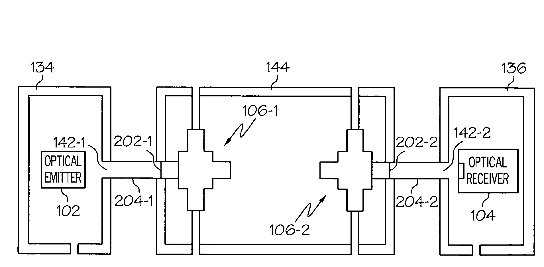
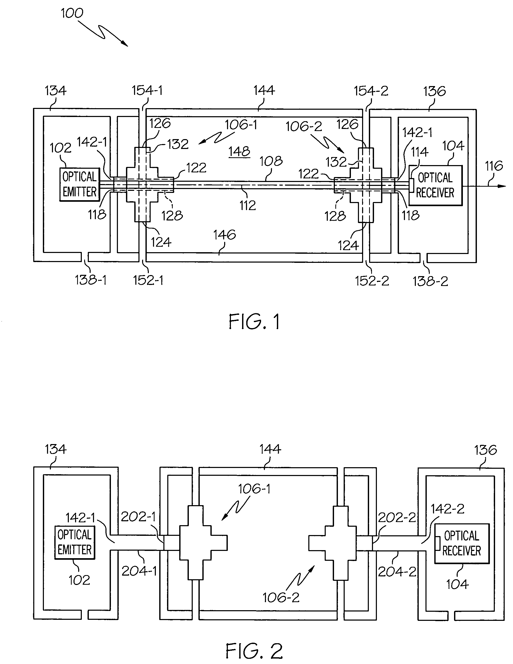
[0016]Turning now to the description, and with reference to FIG. 1, an exemplary gas purged optical densitometer is shown. The depicted densitometer 100 includes an optical emitter 102, an optical receiver 104, and a pair of optical path purge devices 106 (106-1, 106-2). The optical emitter 102, when appropriately energized, is configure...


PUM

PropertyMeasurementUnit
optical densitometeraaaaaaaaaa
optical intensityaaaaaaaaaa
velocityaaaaaaaaaa

Abstract

An advanced gas purged optical densitometer that significantly decreases the likelihood of optical component contamination and unstable optical path reduction includes an optical emitter, an optical receiver, and an optical path purge device. The optical emitter emits a light beam along an optical axis, through the optical purge path device and a test fluid. The optical receiver receives the light beam after it traverses the optical path purge device and the test fluid, and supplies a signal representative of intensity of the received light beam. The optical path purge device is configured to prevent contamination of the optical emitter and optical receiver, and to maintain a substantially optical path length of the test fluid.

Description

TECHNICAL FIELD[0001]The present invention relates to an optical densitometer and, more particularly, to an advanced gas purged optical densitometer that significantly decreases the likelihood of optical component contamination and unstable optical path reductions.BACKGROUND[0002]Various systems and devices have been devised to detect, and measure the density of, various fluids, including gas, as well as particulate that may be suspended within these various fluids. For example, many fire detection systems use densitometers to detect the presence of smoke within an environment. As is generally known, smoke is essentially fine particulates, such as carbon, that are generated by combustion and that are suspended in a gas, such as air. Smoke particulates are typically opaque, or at least reflective. Thus, various types of optical densitometers have been developed that detect the presence of smoke, and in some instances the density of smoke, in a gas by measuring the opacity or optical ...

Claims


Application Information

Patent Timeline
Patent Type & Authority Patents(United States)
IPC IPC(8): G01N21/61
CPCG01N21/15G01N21/534G01N2021/151
Inventor FRIEDRICHS, HANS P.
Owner HONEYWELL INT INC
Learn More