Cooling system for an electronic display

a technology of electronic display and cooling system, which is applied in the direction of indirect heat exchangers, lighting and heating apparatus, instruments, etc., can solve the problems of insufficient heat dissipation system, the market is demanding the size of the display screen, and the heat dissipation system of the past, so as to reduce the amount of dust, improve the cooling capacity, and increase the fluctuation of temperature

Inactive Publication Date: 2008-01-15
HEADY GREGORY S
View PDF14 Cites 11 Cited by
  • Summary
  • Abstract
  • Description
  • Claims
  • Application Information

AI Technical Summary

Benefits of technology

[0010]By the aspects to be described below, the present invention has made consistent cooling possible for electronic displays having screens of sizes greater than or equal to twelve inches. For example, cooling of a fifteen inch screen can be achieved, even in extremely hot climates. The present invention implements insulative materials, improved contact between elements for increased conductive heat transfer, and a two phase refrigerant in conjunction with isolating a volume to be cooled from the compressor and the ambient conditions external to the volume.
[0011]In particular, separating the compressor from the electronics has some important advantages. One advantage is that doing so physically separates the heat creating compressor and associated fins from the electronics that the system is trying to cool. Therefore the present invention lessens the opportunity for the heat from the compressor to be returned to the electronic components. Another advantage is that isolation of the compressor from the electronics permits the present invention to be used in applications that have restrictions on how close certain components may be placed to the displays. For example, refrigerant type cooling systems would typically not be approved for gasoline display pumps because of the fire hazards associated with the contactors that switch the cooling system on and off. However, with the present invention, the compressor and associated components can be isolated from a gasoline pump and display. In fact, ideally, a large compressor may be isolated in a canopy or roof. A regulator may control flow through a plurality of lines communicating between the compressor and a corresponding plurality of pumps. Thus, the present invention advantageously opens possibilities of providing effective cooling in gasoline pump displays and other applications.
[0014]While sealing off a volume in which the electronic components reside may seem counterintuitive in light of the past convective cooling systems, sealing the volume surrounding the electronics has the advantages of reducing the amount of dust that will collect on the components. Furthermore, sealing a smaller volume that more tightly encloses the electronic components reduces the volume or mass that needs to be maintained at a cool temperature. While electronic displays having screens between ten to twelve inches could be cooled to a degree with the convective heat transfer cooling systems of the past, many screens of sizes greater than or equal to approximately twelve inches require improved cooling capabilities such as those of the present invention. In particular, many applications call for fifteen inch screens. With increased heat production with the screens of larger sizes and radiative heat transfer from the sun through the display window, heat dissipation systems of the past that attempt to cool the entire interior of the display with fins and fans are no longer adequate. On the other hand, it is to be noted that fans may also be implemented with the sealed configurations of the present invention. This may provide the advantage of adding convective heat transfer while isolating the electronic components from external dust. The present invention may be sealed to withstand pressures in a range from approximately plus 3.5 psi absolute to approximately minus 3.5 psi absolute. Sealing to this level equates to providing an enclosure that can withstand 800 pounds of force on a display window that corresponds in size to a 15 inch screen. Such sealing has the advantage of assuring that the enclosure will be protected against entry of external ambient air or moisture.

Problems solved by technology

This is not adequate in many climates, especially when radiative heat transfer from the sun through a display window becomes a major factor.
Furthermore, the market is demanding larger screen sizes for displays.
With increased heat production with the fifteen inch screens and radiative heat transfer from the sun through the display window, heat dissipation systems of the past, (which attempt to cool the entire interior of the display with fins and fans), are no longer adequate.

Method used


Image

  • Cooling system for an electronic display
  • Cooling system for an electronic display
  • Cooling system for an electronic display

Examples


Embodiment Construction

[0045]Embodiments of the present invention relate to a cooling system for an electronic display and to combinations of the cooling system and the electronic display. The present invention also relates to a heat collector including a heat collector plate for the cooling system.

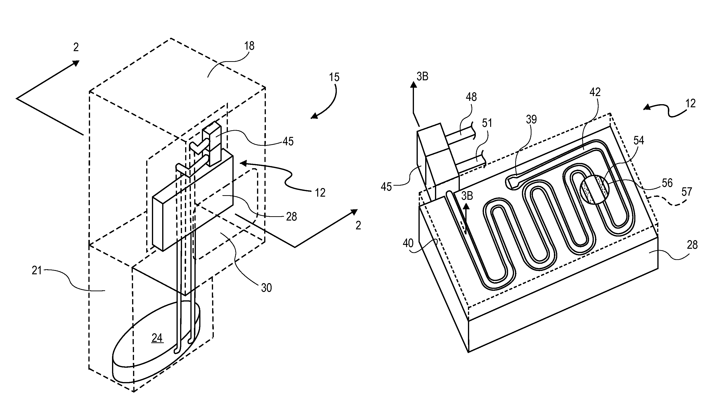
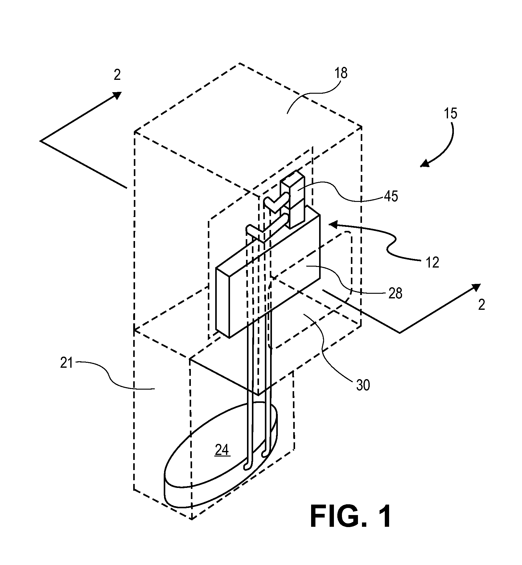
[0046]As shown in FIG. 1, a heat collector 12 may be provided in a display 15 in order to collect and remove excess heat from a compartment 18 and dissipate the excess heat in a location remote from the compartment 18, such as in a housing base 21. In the exemplary view of FIG. 1, the housing base 21 contains a compressor 24. The housing base 21 will also typically include fins or other heat dissipating components and structure associated with the compressor 24.

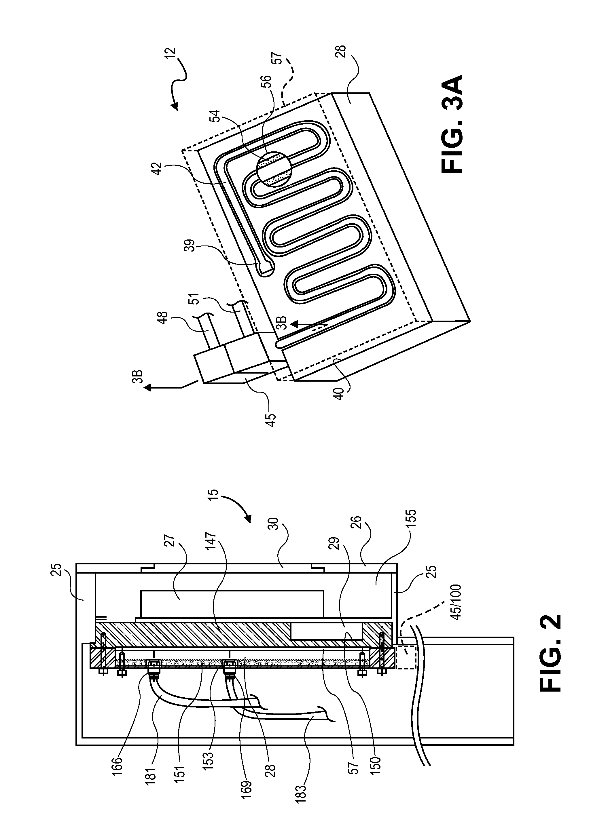
[0047]Advantageously the compartment 18 is a thermally insulated enclosure. For example, in FIG. 2, a cross section of the display 15 taken along lines 2-2 of FIG. 1 shows an alternative embodiment including walls 25, 26, which may be formed of an insula...


PUM


Abstract

A cooling system for an electronic display may include a heat collector plate with internal gas and liquid phase lines. The cooling plate may be thermally isolated together with electronic components of the display within an enclosure of the display, while external lines carry liquid and gas phase refrigerant outside the enclosure to and from the heat collector plate. The external lines may be similar in size to each other and may be connected to the heat collector outside the heat collector plate by a manifold. The heat collector plate contacts a base plate of the electronic display in a thermally conductive relation to transfer heat from electronic components within the display to the gas phase refrigerant. Fans may be included for additional convective heat transfer. A single compressor may be fluidly connected to multiple heat collector plates in respective electronic displays.

Description

[0001]This application claims the benefit of U.S. patent application Ser. No. 10 / 823,477, entitled COOLING SYSTEM FOR AN ELECTRONIC DISPLAY, by the same inventor, filed Apr. 12, 2004 now U.S. Pat. No. 7,161,803, the disclosure of which is incorporated herein by referenceBACKGROUND OF THE INVENTION[0002]1. Technical Field[0003]This invention generally relates to heat collector systems, and in particular to heat collector systems for electronic displays.[0004]2. State of the Art[0005]The prior art predominately includes convective heat transfer systems for electronic displays. These systems of the past generally attempt to remove heat from the electronic components in a display through as many sidewalls of the display as possible. In order to do this, the systems of the past have incorporated fans for moving air past the components to be cooled and out of the display. In some cases, the heated air is moved into convectively thermal communication with fins. Some of the past systems hav...

Claims


Application Information

Patent Timeline
Patent Type & Authority Patents(United States)
IPC IPC(8): H05K7/20F28D7/12F28F7/00
CPCH05K7/2099
Inventor HEADY, GREGORY S.
Owner HEADY GREGORY S
Why Eureka
Try Eureka